Top Flite TOPA0130 User Manual
Page 41
FIT THE FLAPS
DO THESE STEPS FOR OPERATING FLAPS
❏ ❏
1. Mark the locations of the hinges on the
wing and flaps
(You should have already done
this step, but if not, check the wing plans for the
locations).
❏ ❏
2. Use a T-bar to true up the aft edge of
the wing sheeting in the flap section.
❏ ❏
3. Sand a radius from the LE of each
Flap around to the sheeted side (See the cross-
section on the wing plan for the required radius).
❏ ❏
4. Test fit the flaps. Check that all edges
are flush. NOTE: The aft edge of the flaps
should match the aft edge of the wing. Also
the flaps should lie flat against the trailing
edge of the wing.
❏ ❏
5. When a good fit is obtained, install the
Pivot Point Hinges (GPMQ4003). NOTE: The
hinges are not glued in until after the finish has
been applied. Drill 1/8" holes at the hinge
locations. Use a sharp #11 knife to cut a notch
in the leading edge of the flaps at the hinge
locations. This will allow the hinge to pivot in the
center of the flap's LE radius (refer to the
cross-sections on the wing plan).
❏ ❏
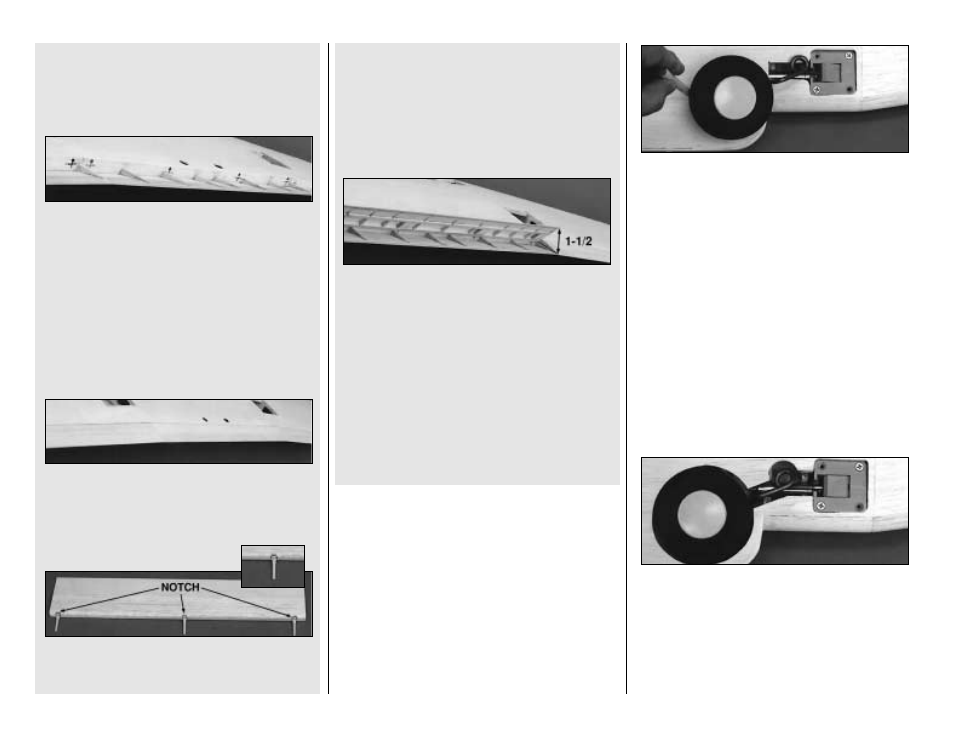
6. Plug the flaps with the hinges into the
wing. Check the fit and run the flaps through
their complete range of motion. The TE of the
flaps should swing 1-1/2" away from the TE of
the wing. Make any required adjustments until
the flaps swing freely. Remember, the flaps must
close flush against the wing TE.
❏ ❏
7. Insert the wire joiners into the brass
tubes and test the operation. Once again,
m a ke a d j u s t m e n t s a s n e e d e d t o a s s u r e
smooth operation.
FINAL FIT THE RETRACTS
DO THESE STEPS FOR OPERATIONAL
LANDING GEAR.
❏ ❏
1. Temporarily install the retract mechanism.
❏ ❏
2. Install the wire landing gear strut and
wheel. Carefully swing the strut down to contact
the wing. Draw a line around the wheel to mark
the area of sheeting to be removed.
❏ ❏
3. Cut away the sheeting from the inside
of the circle, leaving yourself room to make
adjustments with a drum sander.
❏ ❏
4. Cut away as much of the wing rib as
necessary, being careful not to remove more
than required.
❏ ❏
5. Fit the wheel in position. There should
be about 1/8" clearance around the wheel.
❏
6. Repeat steps 1 - 5 for the other side.
41