2 wiring relays, 2 wiring relays -20 – SilentKnight SK-5208 Conventional FACP 10-30 Zone User Manual
Page 30
Control Panel Installation 151204
3-20
3.
Connect the SK-5280 to the SK-5208 control panel as shown in Figure 3-14.
4.
Set the ID number (see Figure 3-13 for ID DIP switch location). See also Section 3.14.1for information on
setting ID numbers.
5.
Reconnect power to the control panel.
Mounting the SK-5280 into the SK-2190 Accessory Cabinet.
Follow these steps to properly mount the SK-5280 into the SK-2190 cabinet:
1.
Mount the remote cabinet using the cabinet mounting holes. See Figure 3-16.
Refer to Section 3.5 for proper cabinet mounting procedures.
2.
Remove power from the control panel.
3.
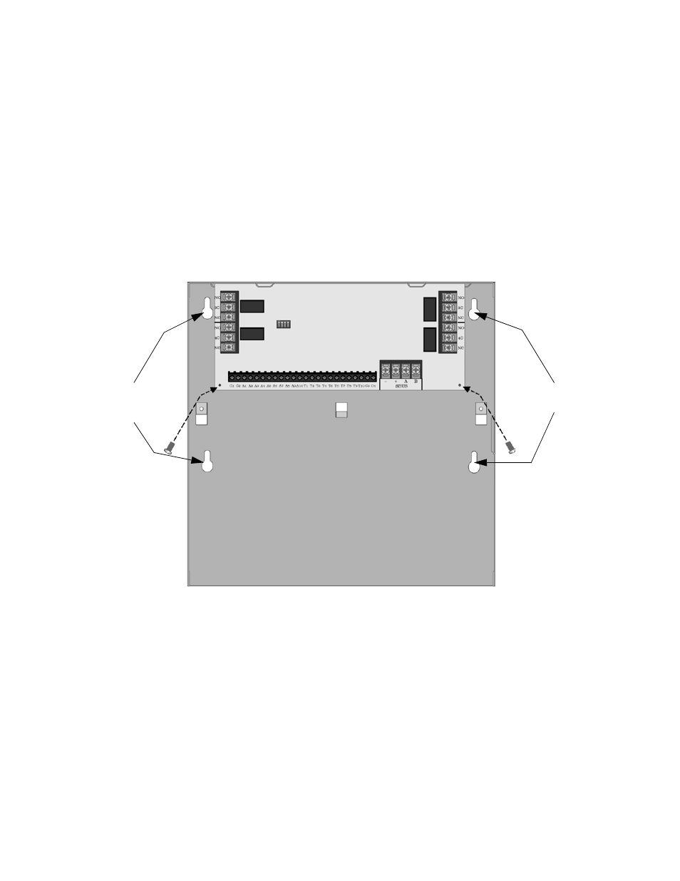
Mount the SK-5280 onto the standoffs and bracket located in the cabinet. See Figure 3-16.
Figure 3-16 Model SK-5280 Remote Installation
4.
Connect the SK-5280 to the SK-5208 control panel as shown in Figure 3-14.
5.
Set the ID number (see Figure 3-13 for ID DIP switch location). See also Section 3.14.1for information on
setting ID numbers.
6.
Reconnect power to the control panel.
3.14.3.2 Wiring Relays
The four on-board relays can be triggered by the active low outputs. For example, the alarm outputs can all be
wired to relay 3 and the trouble outputs can be wired to relay 4
(see Figure 3-17).
Mounting
Holes
Mounting
Holes