2 model sk-5235 remote annunciator, 1 mounting the sk-5235 remote annunciator, 2 model sk-5235 remote annunciator -16 – SilentKnight SK-5208 Conventional FACP 10-30 Zone User Manual
Page 26: 1 mounting the sk-5235 remote annunciator -16
Control Panel Installation 151204
3-16
determine the dip switch positions for each possible ID code.
3.14.2
Model SK-5235 Remote Annunciator
The SK-5235 performs all system operation. It also provides trouble and alarm information and can be used for
programming. The control panel can support up to six SK-5235 Remote Annunciators.
Upon initial power up, the address of each SK-5235 is displayed on the LCD. (Annunciators with address 0 will
not be supervised.)
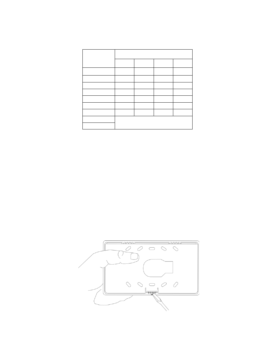
3.14.2.1 Mounting the SK-5235 Remote Annunciator
The SK-5235 Remote Annunciators must be mounted on a dual gang electrical box.
To mount the annunciator:
1.
Remove the rear mounting plate by inserting a #4 flat blade screwdriver into the slots on the bottom edge of
the annunciator. See Figure 3-11. Gently turn the screwdriver until the mounting plate pulls away from the
frame.
Figure 3-11 Rear Mounting Plate Removal
Table 3-5: ID Dip Switch Settings
ID Number
Switches
1
1
2
3
4
0
2
Down
Down
Down
Down
1
Up
Down
Down
Down
2
Down
Up
Down
Down
3
Up
Up
Down
Down
4
Down
Down
Up
Down
5
Up
Down
Up
Down
6
Down
Up
Up
Down
7
Not used
3
8
1.
Switch Settings: Up = On Down = Off
2. Not supervised.
3. ID number 7 and 8 are not valid ID settings.