13 auxiliary relays, 14 accessory devices, 1 setting id codes – SilentKnight SK-5208 Conventional FACP 10-30 Zone User Manual
Page 25: Auxiliary relays -15, Accessory devices -15, Setting id codes -15
Model SK-5208 Installation Manual
151204
3-15
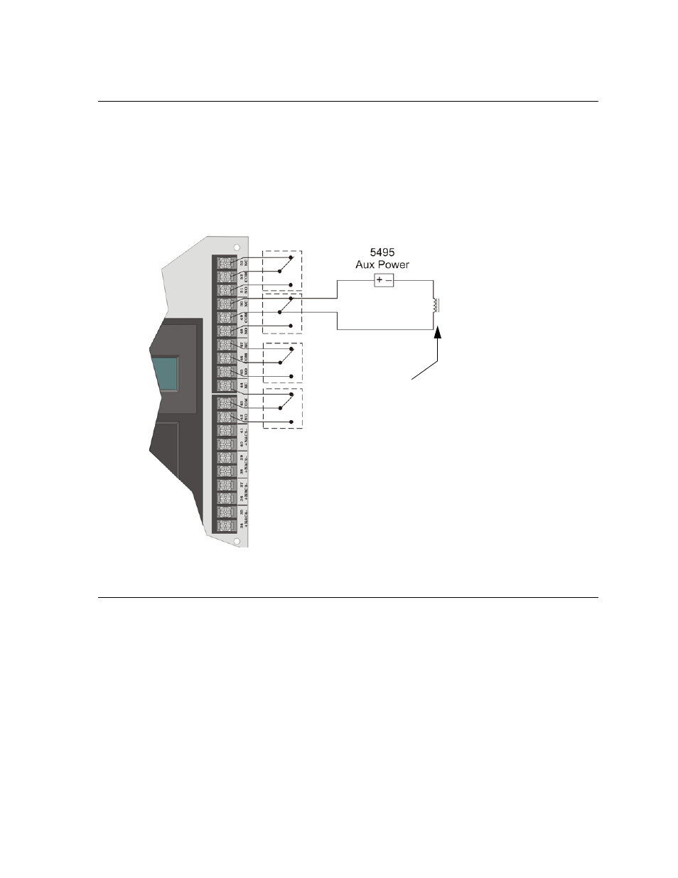
3.13 Auxiliary Relays
The SK-5208 provides four programmable auxiliary relay outputs. Relays can be programmed to activate for the
following conditions, either for all zones or by individual zone: pre-alarm (not acceptable for NFPA 72 Central
Station), fire alarm, auxiliary alarm, alarm by zone, and system or circuit troubles (loss of AC, low battery, failed
to communicate, phone line troubles, fire drills, and notification circuit troubles).
Refer to the SK-5208 programming manual for more information. Figure 3-10 shows the relay contact
connections using a door holder application as an example.
Note: Relays programmed as “Trouble” will be active during normal state and deactivated during a trouble con-
dition.
Figure 3-10 Auxiliary Relays
3.14 Accessory Devices
The section describes how to install the SK-5235 Remote Annunciator, SK-5217 Zone Expander, the 5824
Serial/Parallel Printer Module, and the SK-5280 Status Display Module. All circuits are 24 VDC regulated.
All S-Bus devices are Style 1 Class B as per NFPA 72.
3.14.1
Setting ID Codes
Before installing the SK-5235, SK-5217, 5824 or SK-5280, you must first set their identification codes. Each
device must be given its own identification code. For example: each SK-5235 needs a unique ID code, but a SK-
5235 can have the same ID code as a
SK-5217. Each type of device has it’s own device type programmed into it enabling the control panel to
distinguish between the different devices.
On the back of each device is a small 4-position dip switch used to set the ID code. Use the chart below to
Relay contacts are rated at
2.5 A, 24 VDC/24VAC (inductive rating).
5A, 24 VDC/24 VAC (resistive).
Door Holder
ESL DHX 1224