9 terminal strip description, Terminal strip description -8, Caution – SilentKnight SK-5208 Conventional FACP 10-30 Zone User Manual
Page 18
Control Panel Installation 151204
3-8
Note: The total current draw on smoke power, accessory power, and notification device outputs must not exceed
6A.
3.9
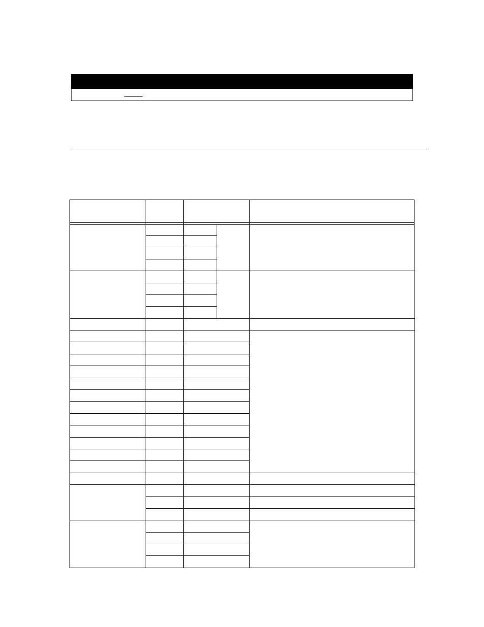
Terminal Strip Description
The terminal strips on the PC board are non-removable. Table 3-4 lists the functions of each terminal. See
Section 3.4 for the board layout.
Caution
Apply AC power before connecting the batteries to the power supply to prevent arcing on battery terminals.
Table 3-4: Terminal Descriptions
Function
Terminal
Number
Terminal Label
Comments
Zone 1 input.
1
A
Z1
Zone 1 input Class A (Style D) or Class B (Style B). See
Section 3.11 for wiring configurations.
2
B
3
C
4
D
Zone 2 input
5
A
Z2
Zone 2 input Class A (Style D) or Class B (Style B). See
Section 3.11 for wiring configurations.
6
B
7
C
8
D
Ground
9
GND
Zone 3 input
10
Z3
Zone input Class B (Style B). Refer to Section 3.11.2.
Power Limited at 100mA. Voltage 27.4 VDC.
Power (Zone 3 & 4)
11
PWR
Zone 4 input
12
Z4
Zone 5 input
13
Z5
Smoke Power
14
PWR
Zone 6 input
15
Z6
Zone 7 input
16
Z7
Smoke Power
17
PWR
Zone 8 input
18
Z8
Zone9 input
19
Z9
Smoke Power
20
PWR
Zone 10 input
21
Z10
Ground
22
GND
AC Power Connections
23
B
24
Earth
25
W
SBUS Connections
26
GND
Used to connect SK-5217 Zone Expanders and 5280
Status Display Modules to the control panel. Accessory
Power (terminals 26 and 27) provides 1 Amp total
current.
27
+24DC
28
A
29
B