2 wiring the sk-5235, 2 wiring the sk-5235 -17 – SilentKnight SK-5208 Conventional FACP 10-30 Zone User Manual
Page 27
Model SK-5208 Installation Manual
151204
3-17
2.
Secure it to the wall using #6 or #8 screws. The mounting plate should be oriented so that the word TOP is
toward the top of the plate and facing you. A square hole is provided in the mounting plate to run the wiring
to the annunciator.
3.
When all of the wires have been connected to the annunciator, set the top of the annunciator over the tabs on
the top of the mounting plate. Make sure the wires do not get pinched between the frame and the mounting
plate. Press each corner of the bottom side onto the annunciator mounting plate until you hear it click. You
may have to gently squeeze the annunciator (top to bottom) to align it while snapping the bottom edge into
place.
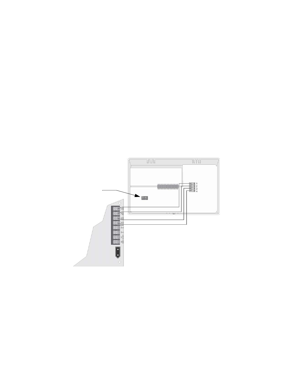
3.14.2.2 Wiring the SK-5235
Follow these steps to properly wire the SK-5235 to the control panel.
1.
Remove power from the control panel.
2.
Wire the SK-5235s as shown in Figure 3-12.
3.
Set the ID number. See Table 3-5.
Note: The ID number of 7 is reserved for the built-in touchpad on the SK
-
5208.
4.
Reapply power the control panel.
When the annunciator powers up, it will display its ID code and current status of the panel.
Figure 3-12 Model SK-5235 Connection
Note: Each 5235 touchpad can be individually supervised. See Section 4.2.2 for programming touchpads as su-
pervised.
ID DIP switches
Supervised
Power Limited
Class B