4 control board components, Control board components -3 – SilentKnight SK-5208 Conventional FACP 10-30 Zone User Manual
Page 13
Model SK-5208 Installation Manual
151204
3-3
3.4
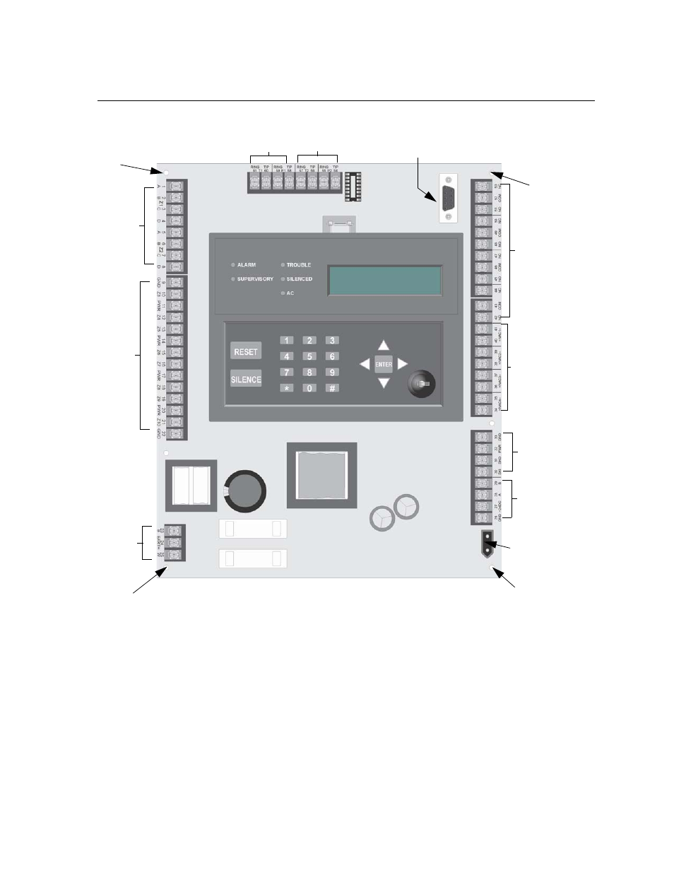
Control Board Components
Figure 3-2 is a wiring diagram for wiring the Model SK-5208 panel.
Figure 3-2 Model SK-5208 Board Layout
Refer to Section 3.9 for complete description of control panel terminal connections.
Figure 3-2 shows the 5208 circuit board stack. If you should need to remove the control board for repair, remove
the four mounting screws which hold the control board in the cabinet. Then lift the control board out of the
cabinet.
Phone Line 1
Connections
Phone Line 2
Connections
NAC
Circuit
Programmable
Output Relays
Backup
Battery
Connector
Connections
Remote
Annunciator
AC
Input
Class A
or
Class B
Zone
Inputs
Class B
Zone
Inputs
SBUS
Connections
RS232
Programming Connector
Mounting
Screw
Mounting
Screw
Mounting
Screw
Mounting
Screw
- 5104 Digital Alarm Communicator Transmitter 6 Zone (48 pages)
- 5128 Digital Alarm Communicator Transmitter (42 pages)
- 5217 10-Zone Expander for 5208 (2 pages)
- 5220 Direct Connect Module (2 pages)
- 5235 Remote Annunciator for 5208 (2 pages)
- 5280 Status Display Module for 5208 (2 pages)
- 5495 6A Distributed Power Module (52 pages)
- 5496 6A Intelligent Remote Power Supply (38 pages)
- 5499 9A Distributed Power Module (56 pages)
- 5600 (114 pages)
- 5660 Silent Knight Software Suite (28 pages)
- 5670 IntelliKnight Facility Management Software (24 pages)
- 5700 (180 pages)
- 5808 (180 pages)
- 5815RMK Remote Mounting Kit (2 pages)
- 5815XL Signal Circuit Expander (2 pages)
- 5820XL-EVS (236 pages)
- 5824 Serial/Parallel Module (2 pages)
- 5860/5860R Remote Annunciator (2 pages)
- 5865-3/5865-4 Remote LED Annunciator (2 pages)
- 5880 LED Driver Module (2 pages)
- 5883 Relay Interface Board (4 pages)
- 5895XL 6A Intelligent Remote Power Supply (56 pages)
- B200S Intelligent Sounder Base with CO Support (4 pages)
- B200S-LF - Low Frequency Intelligent Sounder Base (4 pages)
- B200SR Sounder Base (4 pages)
- B200SR-LF Low Frequency Intelligent Sounder Base (4 pages)
- B210LP 6 Mounting Base (2 pages)
- B224BI 6 Mounting Base w/Built-in Isolator (2 pages)
- B224RB 6 Mounting Base w/Built-in Relay (4 pages)
- B501 4 Mounting Base (2 pages)
- Central Station Monitoring List (1 page)
- Document Revision History (4 pages)
- EVS (74 pages)
- EVS-CE4 (2 pages)
- EVS-RVM (2 pages)
- EVS-VCM (2 pages)
- FFT (1 page)
- FFT-24 (2 pages)
- FFT-24 Installation (1 page)
- FFT-FPJ (1 page)
- FFT-HSC (1 page)
- FFT-STSS and FFT-STSR (2 pages)
- HFS-D (4 pages)
- HFS-MM (1 page)