3 maximum battery standby load, 7 ac wiring, 3 maximum battery standby load -6 – SilentKnight SK-5208 Conventional FACP 10-30 Zone User Manual
Page 16: Ac wiring -6
Control Panel Installation 151204
3-6
10% of zones in alarm, but in no case less then three zones per UL864
3.6.3
Maximum Battery Standby Load
Table 3-3 shows the maximum battery standby load for the SK-5208 based on 24 and 60 hours of standby. The
standby load calculations of line D in the Current Draw Calculation Worksheet (Table 3-2) must be less than the
number shown in Table 3-3 for the battery size used and standby hours required.
Batteries larger then 18 AH will not fit into the SK-5208 cabinet and must be housed in the RBB remote battery
box cabinet. See Section 3.8 for battery installation.
*
Required for NFPA 72 Auxiliary Protected Fire Alarm systems for Fire Alarm Service (City Box) and Remote
Station Protected Fire Alarm systems (Polarity Reversal) and Digital Alarm Communicator/Transmitter
(DACT).
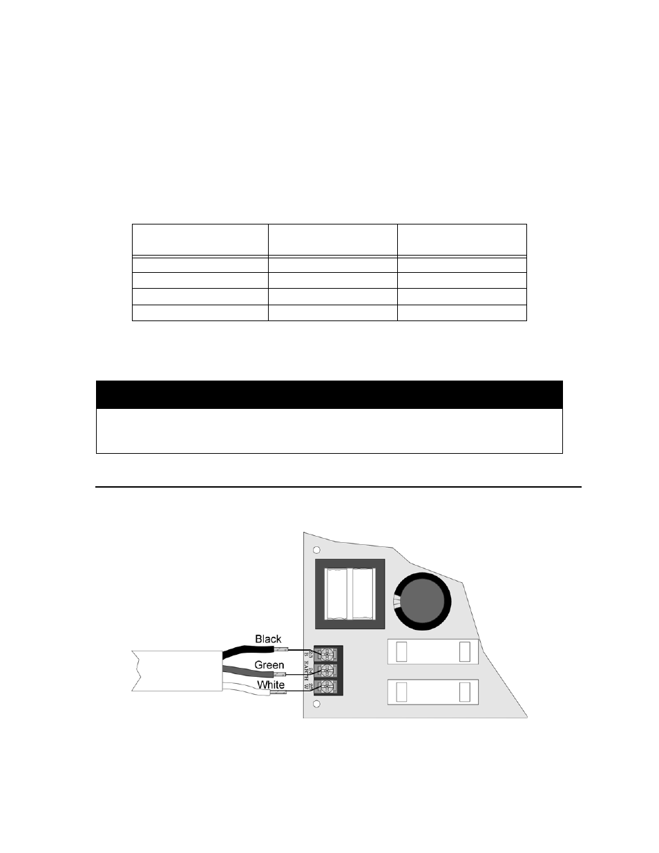
3.7
AC Wiring
The Model SK-5208 power supply delivers 24 VDC at 6A for smoke detector power, notification device power,
and accessory power. Figure 3-3 shows the AC connections to the SK-5208 control panel.
Figure 3-3 AC Wiring
Table 3-3: Maximum Battery Standby Load
Rechargeable Battery Size
Max. Load for 24 hrs.
Standby, 5 mins. Alarm
*Max. Load for 60 hrs.
Standby, 5 mins. Alarm
7 AH
270 mA
105 mA
12 AH
475 mA
190 mA
18 AH
685 mA
270 mA
35 AH
1.1 A
450 mA
Warning!
Silent Knight does not support the use of batteries smaller than those listed in Table 3-3. If you use a battery too small
for the installation, the system could overload the battery resulting in the installation having less than the required 24
hours standby power. Use Table 3-2 to calculate the correct battery amperes/hour rating needed for your installation.