Components 6, Locations of components - cabinet d 6, D cabinet manufactured prior to 8/11 – Reznor MAPSIV RECC Parts Manuals User Manual
Page 6
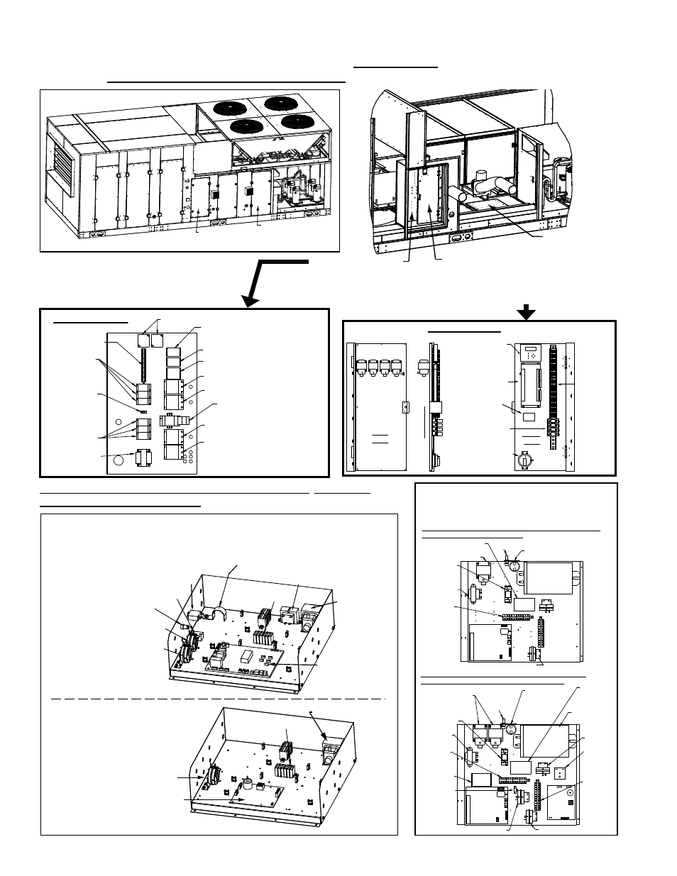
Form P-MAPS III&IV, PN 262958R5, Page 6
High Voltage Panel
(behind low voltage
panel; post is removed
for less restricted view)
Low Voltage Panel
(hinged; swings out
to access rear side and
high voltage panel behind)
Heat Section
Control Panel
(See bottom
of page.)
High Voltage Panel
3 - Control
Transformer
2 - Distribution
Blocks
2 - Distribution
Blocks
7 - Grounding
Lug
Terminal Blocks
1 - Phase Loss
Monitor
5 - Contactor (Condenser
Fan B & C)
5 - Contactor (Condenser Fan A & D)
5 - Contactor (Reheat Compressor E)
5 - Contactor (Compressor D)
5 - Contactor (Compressor C)
5 - Contactor (Compressor B)
5 - Contactor (Compressor A)
72 - Motor Starter or
73 - Line Reactor (See page 11.)
Rear
View
Side V
iew
Front
View
3 - 75VA
transformers
42 - Optional Dirty
Filter Switch or
38 - Pressure Gauge
11 - Digital
Controller
16 - Interface
Board
(Opt AUR1)
10 -
Controller
Display
15 - Relays and
Bases (Optional)
Low Voltage Panel
28 -
Wiring
Harness
Control
Compartment
Access Door
Heat Controls Access
Door (See illustrations
on btm of page.)
Filter Access
Coil Access
Fan and Motor
Access
Condenser Section
A
B
C
D
Electrical Panels showing Locations of Components - Cabinet Size D, Models RCB, RDB, RDCB,
and RDDB (See pages 7-10 for P/N’s and illustrations.)
Locations of Controls in Gas Heat Section of MAPS
®
III Cabinet
Size D (See illustration above.) - Models RDCB and RDDB
Electrical Compartment and Control Components (cont’d)
20 - Venter Motor
Capacitor
3 - 75VA Transformer
3 - Control
Transformer
High
Voltage
Terminal
Blocks
MAPS®III D Cabinet with Heat Section Sizes 500, 600, 700, 800 with
Option AG70, Modulating Gas Control
3 - KVA
Transformer
Ignition
Board
(contact
factory for
replacement)
Ignition
Board
(contact
factory for
replacement)
Low
Voltage
Terminal
Blocks
14 - Air
Proving
Switch
19 - Heat Sequencer
Control Module
15 - Heat
Permissive
Relay and
Base
4 - Fuse
18 - Combustion Air Switch
3 - 75VA
Transformers
3 - Control
Transformer
High
Voltage
Terminal
Blocks
MAPS®III D Cabinet with Two Heat Sections, Sizes 1000, 1200,
1400, 1600 with Option AG70, Modulating Gas Control
23 -
Time
Delay
Relay
14 - Air
Proving
Switch
15 - Heat
Permissive
Relay and
Base
Fuse
Holder
Low
Voltage
Terminal
Blocks
3 - KVA
Transformer
19 - Heat
Sequencer
Control
Module
20 - Venter
Motor
Capacitor
5 - Venter
Contactor
23 -
Ignition
Board
18 - Combustion Air Switch
18 - Combustion Air Switch
24 - Limit
Device
Terminal Blocks
18 - Pressure Switch
(Combustion Air)
3 - Transformer 75VA
23 - Ignition Board
Gas Heat
Section
Electrical Box -
Applies to All Sizes
(furnace with modulating burner)
Gas Heat Section Electrical Box -
Applies only to Sizes 1000, 1200,
1400, 1600 with two furnace
sections (in non-modulating
heat section).
Terminal
Blocks
14 - Pressure
Switch
(Airflow)
18 - Pressure Switch
(Combustion Air)
27 - PAM Relay
Venter Motor Capacitor Bracket, P/N 208921
(20 - Venter Motor Capacitor)
3 - Transformer 30VA
Transformer
75VA
21 - Control Board
with ID Plug (See
CODE 22 on page 8.)
Fuse Holder
P/N 60241
26 - Thermal Circuit
Breaker
Applies to all gas heat section controls on D Cabinet units
manufactured beginning 8/2011 (NOTE: May also apply to units
manufactured as specials prior to 8/11.)
Applies to gas heat section controls
on MAPS
®
D cabinet manufactured
prior to 8/11.
- MAPSIV RDDC Parts Manuals MAPSIV RDCC Parts Manuals MAPSIV RDC Parts Manuals MAPSIV RCC Parts Manuals MAPSIV REDC Parts Manuals MAPSIII RECB Parts Manuals MAPSIII RDDB Parts Manuals MAPSIII RDCB Parts Manuals MAPSIII RDB Parts Manuals MAPSIII RCB Parts Manuals MAPSIV Parts Manuals MAPSIII REDB Parts Manuals