Rating plate 2, Serial no. 2, Reznor – Reznor MAPSIV RECC Parts Manuals User Manual
Page 2: Danger, Rating plates and serial no, Serial no. decoding
Form P-MAPS III&IV, PN 262958R5, Page 2
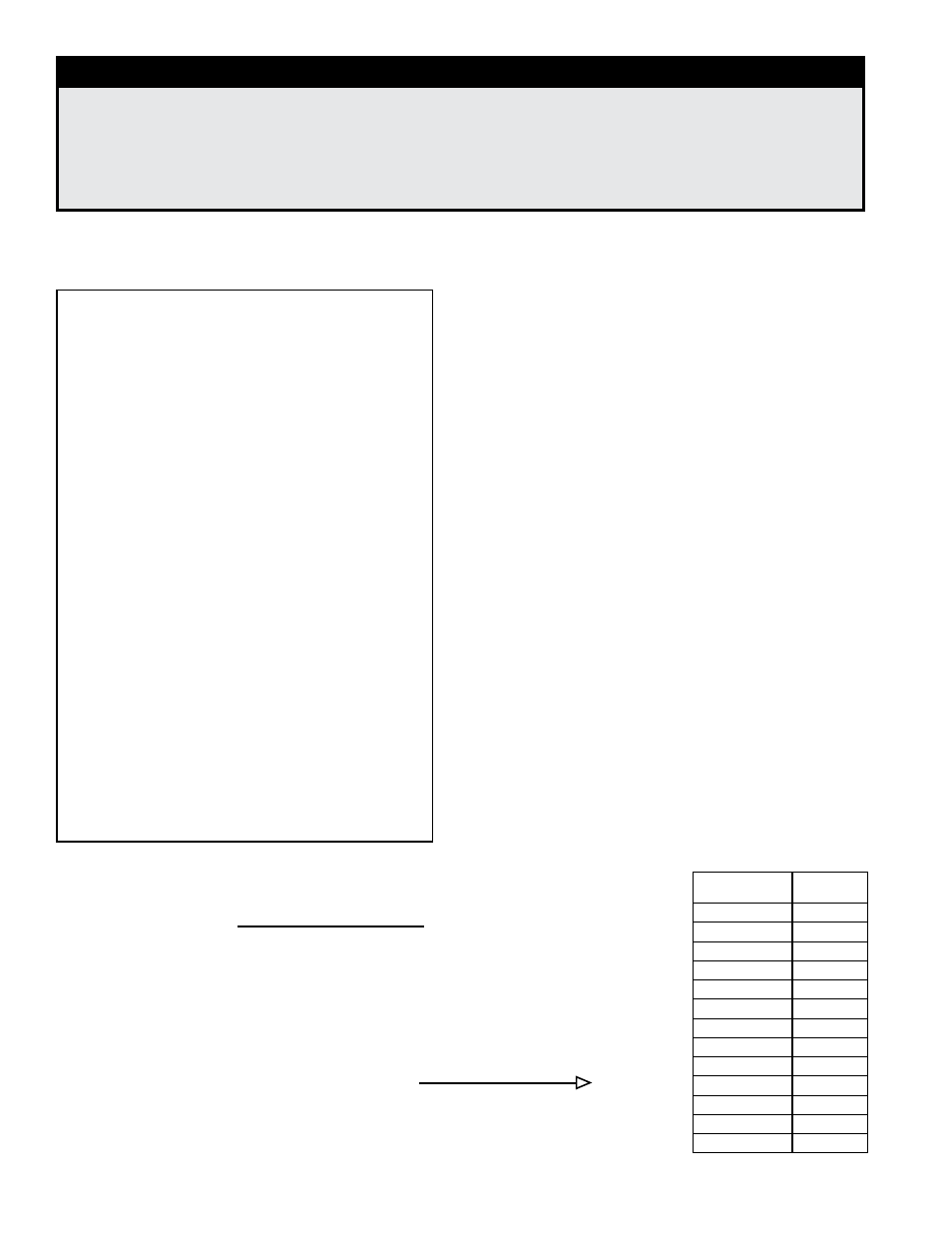
REZNOR
®
MERCER, PA., U.S.A. 16137
MADE IN USA
FOR INDUSTRIAL/COMMERCIAL USE ONLY
SUITABLE FOR OUTDOOR USE
MODEL [ A ]
[ B ]
SERIAL NO. [ ]
ELECTRICAL
[D] VOLTS +/- 10% [D] PHASE [D] HZ
MINIMUM CIRCUIT AMPACITY (MCA)
[ F ] AMPS
MAXIMUM FUSE SIZE/*CKT BREAKER
[ G ] AMPS
QTY
FLA (EA) HP (EA)
SUPPLY AIR BLOWER MOTOR
1
[ E ]
[ C ]
CONDENSER FAN MOTOR (S)
[ T ]
[ U ]
[ Z ]
QTY
RLA (EA) LRA (EA)
COMPRESSOR A
[ H ]
[ I ]
[ J ]
COMPRESSOR B
[ K ]
[ L ]
[ M ]
COMPRESSOR C
[ N ]
[ O ]
[ P ]
COMPRESSOR D
[ Q ]
[ R ]
[ S ]
COMPRESSOR E
[ GG ]
[ HH ]
[ II ]
CIRCUITS
A
B
C
D
E
REFRIGERANT - R-410a CHARGE - LBS
[ V ] [ W ] [ X ] [ Y ] [ JJ ]
TEST PRESSURES
HIGH
600 PSIG LOW
45 PSIG
EQUIPPED FOR OPERATION AT AN AIR FLOW OF
[ CC ] SCFM
AGAINST A STATIC PRESSURE OF
[ DD ] INCHES WATER COLUMN
DRIVE RPM
[ EE ]
WIRE DIAGRAM
[ FF ]
REFER TO RATING PLATE IN THE FURNACE SECTION (WHEN USED)
FOR ADDITIONAL INFORMATION.
*HACR TYPE REQUIRED PER NEC
System Rating Plate Key:
A = Model
B = Manufacturing Date
(Month/Year)
C = Blower Motor HP
D = Volts/Phase/Hertz
E = Full Load Amps (FLA) of
Blower Motor
F = Minimum Circuit
Ampacity (MCA)
G = Maximum Fuse Size
(MOP)
H = Quantity - Compressor A
I = Rated Load Amps of
Compressor A
J = Locked Rotor Amps of
Compressor A
K = Quantity - Compressor B
L = Rated Load Amps of
Compressor B
M = Locked Rotor Amps of
Compressor B
N = Quantity - Compressor C
O = Rated Load Amps of
Compressor C
P = Locked Rotor Amps of
Compressor C
Q = Quantity - Compressor D
R = Rated Load Amps of
Compressor D
S = Locked Rotor Amps of
Compressor D
T = Quantity Condenser Fan
Motors
U = Rated Load Amps of
Condenser(s)
V = Refrigerant Charge (lbs) -
Circuit A
W = Refrigerant Charge (lbs)
- Circuit B
X = Refrigerant Charge (lbs) -
Circuit C
Y = Refrigerant Charge (lbs) -
Circuit D
Z = Condenser Fan Motor HP
CC = SCFM Airflow
DD = External Static
Pressure (“ w.c.)
EE = Drive (Option AM)
FF = Wiring Diagram No.
GG = Quantity - Compressor
E
HH = Rated Load Amps of
Compressor E
II = Locked Rotor Amps of
Compressor E
JJ = Refrigerant Charge (lbs)
- Circuit E
Rating Plates and Serial No.
Serial No. Decoding
Decoding a System Serial No.
Serial No. Sample:
3 BIJ 789 BK 08 N 96 7D
Elements of No.:
1| 2 | 3 | 4 | 5 |6| 7 | 8
Elements 1-5 apply to all models.
Elements 6-8 apply to models with gas heat section (RCDB, RDDB, RCDC, RDDC).
K
ey: 1 = Phase (1 or 3)
2 = Date CODE (See table top of page 3.)
3 = Consecutive number
4 = Drive (See drive components on pages 12-16.)
5 = Motor HP (See explanation on the right.)
6 = Type of Gas - Models RDCB, RDDB, RDCC, RDDC (N = Natural; L = Propane)
7 = Ignition CODE - Models RDCB, RDDB, RDCC, RDDC (See Form P-Valves.)
8 = Valve CODE - Models RDCB, RDDB, RDCC, RDDC (See Form P-Valves.)
Motor HP
Serial No.
Code
1/2
03
3/4
04
1
05
1-1/2
06
2
07
3 (3450 rpm)
08
5 (3450 rpm)
09
7-1/2
11
15
12
10
13
20
14
3 (1800rpm)
15
5 (1800rpm)
16
Sample of System Rating Plate (applies to all models)
DANGER
This unit contains R-410A high pressure refrigerant. Hazards exist that could result
in personal injury or death. Installation, maintenance, and service should only be
performed by an HVAC technician qualified in R-410A refrigerant and using proper
tools and equipment. Due to much higher pressure of R-410A refrigerant, DO NOT
USE service equipment or tools designed for R22 refrigerant.
- MAPSIV RDDC Parts Manuals MAPSIV RDCC Parts Manuals MAPSIV RDC Parts Manuals MAPSIV RCC Parts Manuals MAPSIV REDC Parts Manuals MAPSIII RECB Parts Manuals MAPSIII RDDB Parts Manuals MAPSIII RDCB Parts Manuals MAPSIII RDB Parts Manuals MAPSIII RCB Parts Manuals MAPSIV Parts Manuals MAPSIII REDB Parts Manuals