Electrical compartment 5, Electrical compartment and control components, See pages 7-10 for p/n’s and illustrations – Reznor MAPSIV RECC Parts Manuals User Manual
Page 5
Form P-MAPS III&IV, PN 262958R5, Page 5
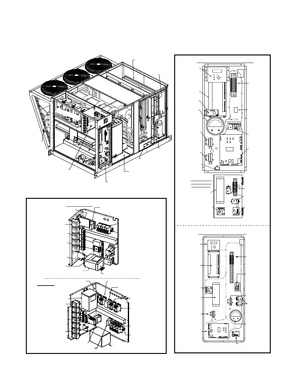
Electrical Compartment and Control Components
Electrical Panels Showing Access showing Locations of High and Low Voltage Control
Components - Cabinet Sizes A, B, and C, Models RCB, RDB, RDCB, RDDB, RECB, REDB, RCC,
RDC, RDCC, RDDC, RECC, and REDC
See pages 7-10 for P/N’s and illustrations.
Low Voltage Panel (top right)
High Voltage Panels
Tubing
Access
Condenser Section
Heat Section
(Gas illustrated)
Reheat
Compressor
Slide-out
Filter Rack
Compressors
Dampers
Evaporator Coil
Section (slide
out drain pan)
Blower Section
with Bottom Discharge
10 - Controller
Display
(BacView)
11 - IQ
Controller
16 - Reheat
Board
18 - Combustion
Air Proving
Switch
(RDCB/RDCC/
RDDB/RDDC)
14 - Air
Proving
Switch
17 - Power Supply
21 - Control
Board w/ID Plug,
Code 22 page 8.
(RDCB/RDCC/
RDDB/RDDC)
19 -
Sequencer
(RDCB/RDCC/
RDDB/RDDC)
12 - Control
Expander
Option BHB6
38 - Differential
Pressure
Gauge or
42 - Dirty Filter
Switch
Low Voltage Panel - Cabinet C
40/41 -
Optional
Control
Block(s)
28 - Wiring
Harness
10 - Controller
Display
(BacView)
11 - IQ
Controller
13 - Optional
Plugin Card
38 - Optional
Differential
Pressure
Switch or
42 - Dirty Filter
Switch
18 - Combustion
Air Proving
Switch
(RDCB/RDCC/
RDDB/RDDC)
14 - Air Proving
Switch
20 - Venter Motor
Capacitor
(RDCB/RDCC/
RDDB/RDDC)
21 - Control
Board with ID
Plug (See Code
22, page 8.)
(RDCB/RDCC/
RDDB/RDDC)
19 - Sequencer
(RDCB/RDCC/
RDDB/RDDC)
Primary Low Voltage Layout - Cabinets A & B
12 - Optional
Control
Expander
16 - Optional
Reheat
Board
40/41 - Optional
Control
Block(s)
17 - Power
Supply
Secondary Low
Voltage Layout -
Cabinets A & B
27 - Relay
28A - Wiring
Harness
28B - Wiring
Harness
3 - Control
Transformers
5 - Contactor,
Compressor A
5 - Contactor,
Compressor B
5 - Contactor, Compressor C
(below “B”, behind the transformer)
71/72 - Contactor
or Starter and
Overload,
Blower Motor
5 - Contactor, Compressor DH
1 - Phase Monitor
or Motor Saver
5 - Contactor,
Condenser Fan
7 - Grounding
Lug
2 - Distribution
Blocks
Cabinets A & B
Cabinet C
5 - Contactor,
Compressor DH
4 - Fuse
6 - Digital Controller
- MAPS® IV only
3 - Optional Transformer
2 - Distribution
Blocks
5 - Contactor,
Condenser Fan
5 - Contactor, Compressor A
5 - Contactor,
Compressor B
5 - Contactor,
Compressor C
71/72 - Contactor
or Starter and
Overload,
Blower Motor
3 - Control
Transformers
3 - Optional
Transformer
3 - Optional Transformer
1 - Phase Monitor or Motor Saver
7 - Grounding
Lug
4 - Fuse
6 - Digital Controller
- MAPS® IV only
- MAPSIV RDDC Parts Manuals MAPSIV RDCC Parts Manuals MAPSIV RDC Parts Manuals MAPSIV RCC Parts Manuals MAPSIV REDC Parts Manuals MAPSIII RECB Parts Manuals MAPSIII RDDB Parts Manuals MAPSIII RDCB Parts Manuals MAPSIII RDB Parts Manuals MAPSIII RCB Parts Manuals MAPSIV Parts Manuals MAPSIII REDB Parts Manuals