Reznor PDH Operation Manual PreevA User Manual
Page 9
Form O-PreevA, P/N 234661R8, Page 9
Abnormal Heat Cycle
Functions
Interrupted Call for Heat - If the system controller call for heat is removed before the
flame is recognized, the circuit board will run the venter motor for the post purge period
and de-energize all outputs.
If the call for heat is removed after successful ignition, the circuit board will de-energize
the gas valve and run the venter motor through post purge.
Ignition Retry - If flame is not established on the first trial for ignition period, the igni-
tion system circuit board de-energizes the gas valve, and the venter motor remains
1) Call for Heat - The heating/cooling system controller calls for heat. The ignition sys-
tem circuit board checks to see that the limit switch is closed and the pressure switch is
open. If the limit switch is open, the circuit board responds as defined in the “Abnormal
Heat Cycle, Limit Switch Operation”. If the pressure switch is closed, the circuit board
will do four flashes on the green LED and wait indefinitely for the pressure switch to
open. If the pressure switch is open, the circuit board proceeds to prepurge.
2) Prepurge - The circuit board energizes the venter motor and waits for the pressure
switch to close. If the pressure switch does not close within 30 seconds of the venter
motor energizing, the circuit board will do two flashes on the green LED. The circuit
board will leave the venter motor energized indefinitely as long as the call for heat
remains and the pressure switch is open.
When the pressure switch is proven closed, the circuit board begins the prepurge time.
If flame is present any time while in prepurge, the prepurge time is restarted. If flame is
present long enough to cause lockout, the circuit board responds as defined in “Fault
Modes, Undesired Flame”.
The ignition system circuit board runs the venter motor for a 20 second prepurge time,
then proceeds to the ignition trial period.
3) Ignition Trial Period - The ignition system circuit board energizes the spark and
main gas valve. The venter remains energized. If flame is sensed during the first 16
seconds, the spark is de-energized. If flame has not been sensed during the first 16
seconds, the control de-energizes the spark output and keeps the gas valve energized
for an additional one second flame proving period. If flame is not present after the
flame proving period, the control de-energizes the gas valve and proceeds with ignition
re-tries as specified in “Abnormal Heat Cycle, Ignition Retry”. If flame is present, the
circuit board proceeds to steady heat.
4) Steady Heat - Circuit board inputs are continuously monitored to ensure limit and
pressure switches are closed, flame is established (sensor on both burner sections),
and the system controller call for heat remains. When the call for heat is removed, the
ignition system circuit board de-energizes the gas valve and begins postpurge timing.
5) Post Purge - The venter motor output remains on for a 45 second postpurge period
after the system controller is satisfied.
Normal Heat Cycle
Operating Sequence
3.3.6 Ignition Control
Module for Gas Heat
Section - applies
to all gas controls
EXCEPT Options
D12G and AG58
DSI Integrated Control Module (circuit board) - The module monitors the operation
of the heater including ignition. The only replaceable component is the 3 amp Type
ATC or ATO fuse. If the fuse is blown, the problem is most likely an external overload.
Correct the problem and replace the fuse.
Do not attempt to disassemble the control module. However, each heating season
check the lead wires for insulation deterioration and good connections.
Proper operation of the direct spark ignition system requires a minimum flame signal of
1.0 microamps as measured by a microampmeter.
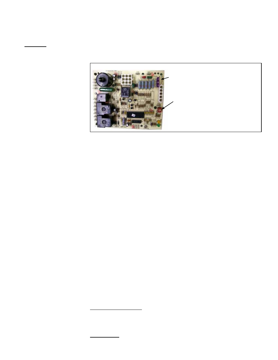
DSI Integrated Control Module (Circuit Board), P/N 195573
Only replaceable part is a type
ATC or ATO 3 amp fuse (Color
Code Violet), P/N 201685
Set “blower off” dip switch setting
to 45 seconds for makeup air
application. Refer to the table on
the control for the appropriate
settings.
Reference: For
Troubleshooting and
explanation of LED
lights, see Paragraph
4.1.