0 maintenance and service information (cont’d), Electric heat panel, Main electrical box control panel fuse panel – Reznor PDH Operation Manual PreevA User Manual
Page 6: 2 control locations (cont’d)
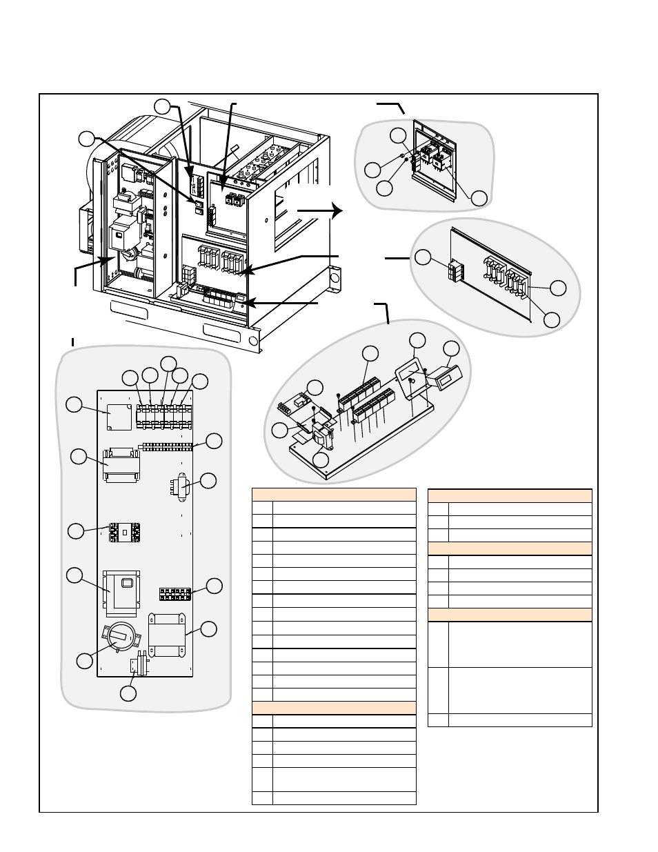
Form O-PreevA, Page 6
FIGURE 1B - Standard and Optional Control Locations - Electric Heat Models PEH and REH
Electric Heat Panel
Discharge
Airflow
Main
Electrical
Box
Control
Panel
Fuse
Panel
50
1
3
4
5
6
7
8
9
10
11
15
14
12
2
13
20
21
22
23
24
25
30
31
32
40
41
42
43
52
Main Electrical Box
1
Exhaust Relay
2
Cool Relay
3
Damper Permissive Relay
4
Speed Change Relay
5
Blower/Damper Relay
6
Phase Loss Relay
7
Evaporative Cooler Transformer
8
Compressor Contactor
9
VFD or Motor Starter
10 Dirty Filter Switch
11 Air Proving Switch
12 460, 575/240 KVA Transformer
13 Line Voltage Terminal Blocks
14 FX06 Transformer
15 Terminal Blocks
Control Panel
20 Terminal Block 24V
21 Controller Bracket
22 FX06 Controller
23 Transformer
24 Relay Mounting Track (with
reheat/dehumidification only)
25 Relay (with reheat/dh only)
Fuse Panel
30 Fuse Block
31 Fuse
32 Distribution Block
Electric Heat Panel
40 Contactor
41 Strain Relief
42 Bushing
43 Terminal Block
Other Electric Heat Section Controls
50 Staging Panel used in some
Option D12D controls (depends
on size and voltage) is on the
Electric Heat Header Panel
51 SCR Power Controller(s) with
Heatsink in Option D12D is on
the Cabinet (side, front, or both)
- See FIGURE 1C.
52 Transformer(s)
2.0 Maintenance and Service Information (cont’d)
2.2 Control Locations (cont’d)