2 control locations – Reznor PDH Operation Manual PreevA User Manual
Page 5
Form O-PreevA, P/N 234661R8, Page 5
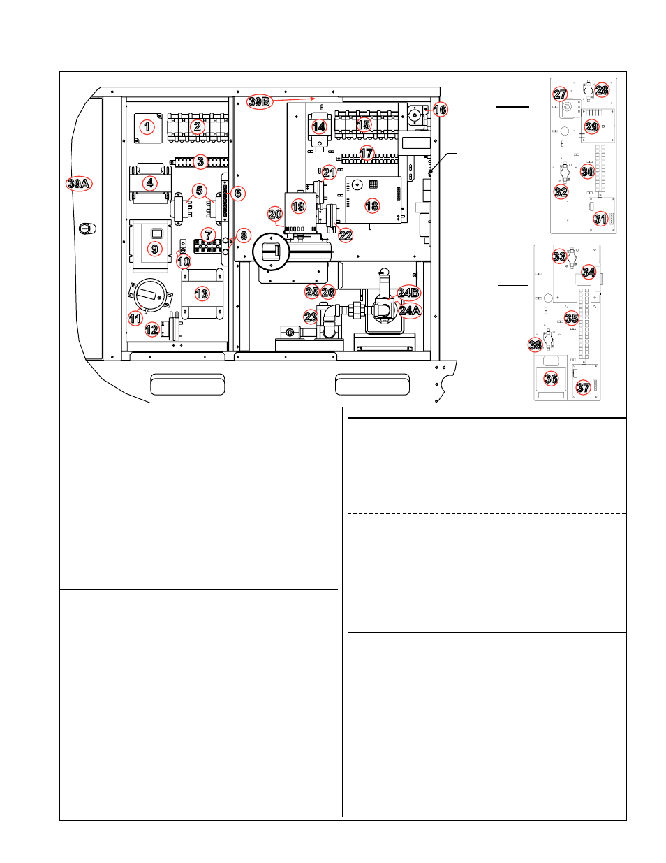
FIGURE 1A - Standard & Optional Control Locations - Models PDH, SDH, RDH, SHH, PXH, RHH, RXH
1
2
3
4
5
6
7
8
9
10
11
12
13
14
15
16
17
18
19
20
21
22
23
24B
25 26
28
29
30
31
35
36
Control Side Electrical Compartments (Doors & cabinet post are removed.)
39A
39B
Secondary
Panel
Location
Secondary
Panel for
Analog AG
Control
Options
Secondary
Panel for DG
and D12
Digital
Control
Options
24A
32
37
27
34
38
33
In the Left Electrical Compartment (high voltage and
low voltage):
1) Optional Phase Loss Control (Option BF)
2) Plug-in Relays
3) Terminal Blocks
4) Transformer (for optional evaporative cooling module)
5) Transformers (right for controller; left for signal conditioner)
6) Terminal Board for thermostat
7) Line Voltage Terminal Blocks
8) Fuse Holders
9) Motor Starter or Variable Frequency Drive (Option VFD)
10) Grounding Lug
11) Optional Dirty Filter Switch (Remote Console Option)
12) Air Proving Switch
13) Transformer (venter motor, 460 & 575 volt PDH/SDH/RHH/
SHH, plus 208 & 230 volt SHH & RHH)
Primary Panel in the Heat Section Electrical
Compartment (low voltage):
14) Transformer (damper)
15) Plug-in Relays
16) High Temperature Limit Control
17) Terminal Blocks
18) Integrated Control Module (circuit board)
19) Venter Motor
20) Venter Motor Capacitor (hidden by venter motor)
21) High Speed Combustion Air Pressure Switch
22) Low Speed Combustion Air Pressure Switch (units with
2-speed venter, Opts AG 40, 60, 61, 62; DG 1, 2, 5, 6; D12
B, C)
or Models RHH, SHH - Condensate Pressure Switch
Gas Train Components (for D12G or AG58, see page 12):
23) Single-Stage or Two-Stage Gas Valve)
24A) Pressure Switch for Modulation (Options AG40; DG 2 & 6;
and D12B)
24B) Modulating Gas Valve (Options AG40; DG 2 & 6; & D12B)
25) Optional High Gas Pressure Switch (Opt BP2 not shown)
26) Optional Low Gas Pressure Switch (Opt BP3 not shown)
Secondary Panel in the Heat Section Electrical
Compartment with Analog Controls (low voltage):
27) Unit-Mounted Ductstat (Options AG 3, 60)
28) Time Delay Relay (Venter)
29) Optional Freezestat (Option BE2)
30) Terminal Blocks
31) Optional Venter Speed Controller (Opts AG 58, 60, 61, 62)
32) Time Delay Relay (Speed change, Opts AG 58, 60, 61, 62)
Secondary Panel in the Heat Section Electrical
Compartment showing low voltage Digital Controls
and Opt AG40 for field-supplied computer control:
33) Time Delay Relay (Venter)
34) Programmable Controller (Opts DG 1, 2, 5, 6; D12 B/C/F/G)
35) Terminal Blocks
36) Signal Conditioner (Options DG 2, 6; AG40; D12 B, C)
37) Venter Speed Cntrllr (Opt DG 1, 2, 5, 6; AG40; D12 B/C/G)
38) Time Delay Relay (Speed change, Opts DG 1, 2, 5, 6;
AG40; and D12 B/C/G)
Other:
39A) Reverse Flow Limit Switch (in the blower cabinet on RDH/
PDH/SDH Sizes 75-150)
39B) Reverse Flow Limit Switch (on heat section wall above
the electrical compartment on RDH/PDH/SDH Sizes 175-
400A and all RHH and SHH)
40) Safety Door Switch (SDH and SHH) on Heat Section Door
(not shown in
FIGURE 1A)
41) Optional Convenience Outlet (Option BC2) - requires its
own electrical supply (on the cabinet panel below the left
electrical compartment door; not shown in
FIGURE 1A)
42) Optional Lockable Service Switch (Option BA6) (on the
cabinet panel below the left electrical compartment door;
not shown in
FIGURE 1A
43) Vent Temperature Limit (RHH & SHH)
2.2 Control Locations