Reznor PDH Operation Manual PreevA User Manual
Page 11
Form O-PreevA, P/N 234661R8, Page 11
3.3.7 Ignition Control
Module and Spark
Board for Gas Heat
Section with Option
AG58 or D12G -
applies to RDH Sizes
175-400, RHH, & SHH
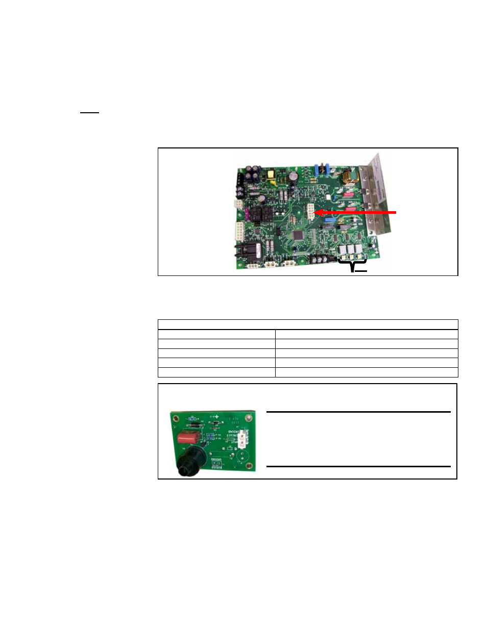
Integrated Control Module for Gas Control Options AG58 and D12G -
The con-
trol module is located in the control compartment with an additional board to
control spark that is attached to the removable shield on the end of the burner.
Except for the replaceable parts shown, do not attempt to disassemble either
board. Each heating season check the lead wires for insulation deterioration
and good connections.
If replacement is required, these boards must be replaced with identical parts.
Integrated
Control
Module (Circuit
Board) used
in Gas Control
Options AG58
and D12G
The control has a built-in, self-diagnostic capability. The control continuously monitors
its own operation and the operation of the heat section including direct spark ignition,
safety and modulating valves, and venter motor speed. The 3-digit display on the con-
trol indicates the current system state, warnings, failures, and test modes.
3-Character Display
ID Plug
(unique by
size and
type of gas)
LED 3-Character Display (displayed on power up)
Display Info (example only)
Description
RDH
Furnace series or model name
400
Heat Section Size
nAt or LP
Fuel type
1.01
Software version
IMPORTANT: The board
has an ID plug that is
unique for each model,
size, and type of gas. A
replacement board will
require either a new ID plug
or reuse of the ID plug from
the board being replaced.
REFERENCE:
Operating and Lockout
Error Codes displayed
on the ignition
controller 3-character
display are listed
in Troubleshooting
Paragraph 4.2.
Power interruptions of less than 80mS shall not cause the circuit board to change
operating states. Power interruptions greater than 80mS may cause the circuit board
to interrupt the current operating cycle and re-start.
Spark Ignition Board, P/N 257975, is located on the removable shield
at the end of the burner.
CAUTION: Due to high voltage on
the spark wire and electrode, do not
touch when energized. See Hazard
Levels, page 2.
1) Call for Heat - The FX06 controller or 7350M thermostat calls for heat (there is a
closure between "R" and "W" and at least 2 VDC to the analog input). The ignition sys-
tem circuit board will check the modulating valve position and move to lightoff position.
It checks to see that the limit switch is closed and the pressure switch is open. If the
pressure switch is closed, the circuit board will wait indefinitely for the switch to open.
If the switch is open, the circuit board proceeds to prepurge.
2) Prepurge - After the actuator moves to its lightoff position, the circuit board ener-
gizes the venter motor and waits for the pressure switch to close. If the pressure switch
does not close at the beginning of a heat cycle, the venter motor will run for two min-
utes, then cycle off for 30 seconds, then on for two minutes, and so forth indefinitely.
When the pressure switch is proven closed, the venter motor ramps up to the appropri-
ate lightoff speed and the circuit board begins the prepurge time. If flame is present any