7 optional cooling coil module, 0 maintenance procedures (cont’d), 6 dampers and controls (cont’d) – Reznor PDH Operation Manual PreevA User Manual
Page 20
Form O-PreevA, Page 20
Mixed Air
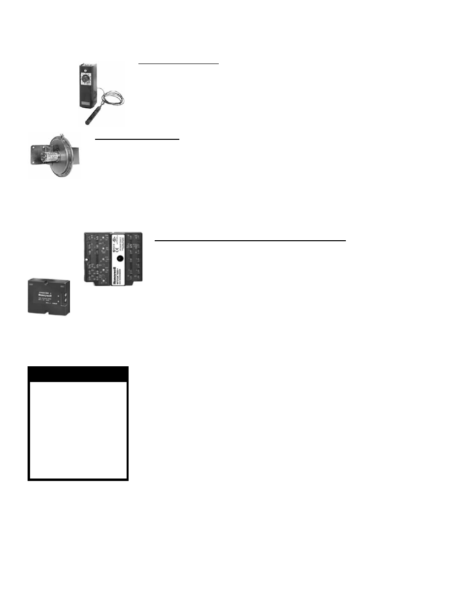
Controller,
P/N 16109
Pressure Null
Switch,
P/N 88052
Economizer
Logic
Module,
P/N 220637
Enthalpy Sensor,
P/N 196290
Economizer Logic Module and Enthalpy Sensor (Options GE 21, 22)
Function: The economizer logic module is used in makeup air cooling applica-
tions to control the outside air damper to provide the most economical inlet air
mixture. During economizer logic module operation, the mechanical cooling is
operated by stage 2 cooling on the space thermostat. The economizer logic mod-
ule is automatically locked out during heating and holds the outdoor air damper at
the minimum position setting.
Service: Check wiring connections. If the economizer logic module or sensor
needs replaced, replace it with an identical control.
Pressure Null Switch (Option GE15)
Function: The pressure null switch is a diaphragm operated differential pressure switch used in
makeup air applications to control building pressure. It maintains a selected positive or negative
pressure setpoint by changing the amount of outside air being introduced to the building through
the modulating outside air dampers. As more pressure is required in the building, the pressure null
switch activates the damper motor driving the outside air damper towards the full open position and
the recirculated air damper towards the closed position. Conversely, as less pressure is required,
the switch drives the dampers in the opposite direction.
Service: Check wiring connections and sensor tubes. If the controller needs replaced, replace it
with an identical control.
3.7 Optional Cooling
Coil Module
3.7.1 Cooling Coil
Inspect the cooling coil at the beginning of the cooling season or more often if needed.
Open the coil cabinet door. Inspect the coil for debris, dirt, grease, lint, mold, or any
element which would obstruct heat transfer or airflow. Inspect coils and tubing for
physical damage. Inspect feeders, piping connections, coil headers, and return bends
for signs of fatigue, rubbing, and physical damage.
To clean the coils, use the proper tools and follow the instructions carefully to avoid
damaging the coil. Use of a non-acid based coil cleaner is recommended. Due to pos-
sible damage to the coil, high pressure spray is not recommended.
Instructions:
1. Verify that the electrical power has been turned off and disconnect switch locked.
2. Open the coil cabinet door.
3. Use a soft brush to remove any dirt and debris from both sides of the coil.
4. Spray with cold or warm (not hot) water and a cleaning solution (non-acid based
coil cleaner is recommended). Due to possible damage to the coil, high pressure
spray is not recommended. First spray the leaving airflow side, then the inlet
airflow side. As much as possible, spray the solution perpendicular to the face of
the coil. Follow the instructions on the cleaning solution. When cleaning process is
complete, rinse both sides with cool, clean water.
3.6 Dampers and Controls (cont’d)
3.0 Maintenance Procedures (cont’d)
WARNING
If equipped with
optional ultra-
violet light, DO
NOT use light for
service lighting.
Never expose eyes
or skin to ultra-
violet light.
Mixed Air Controller (Options GE 11, 12, 13, 14)
Function: The mixed air controller senses the temperature of the air entering the
heater. It automatically operates the damper motor to modulate the outside and return
air dampers based on the temperature setting. When in the heating mode, the tem-
perature of the “mixed” return and outside air entering the heater must always be 35°F
or above.
Service: If the controller does not function properly, replace it with an identical control.
3.7.2 Condensate Pan
and Drain
At the beginning of the cooling season or more often if needed, clean the cooling cabi-
net condensate drain pan, traps, and piping. The drain pan will slide out of the unit for
cleaning. To remove the drain pan, disconnect the drain, remove the screws holding
the small plate around the drain, remove the grommet, remove the plate, and carefully
slide out the drain pan. (See
FIGURE 8.)
After cleaning, re-install all parts and fill traps with water to ensure proper operation.
The combination of airborne particles and moisture in the air handler can result in