0 maintenance procedures -30, 1 filters - all models, 2 belt, blower, and motor - all models – Reznor PDH Operation Manual PreevA User Manual
Page 7: 0 maintenance procedures, Side view - peh
Form O-PreevA, P/N 234661R8, Page 7
3.1 Filters - All Models
Check the filters.
Clean permanent filters, allow to dry, and re-install.
Replace dirty disposable filters. Exposure to humid makeup air can accelerate filter
degradation. Systems with disposable filters require more frequent filter inspection.
Remove dirt and grease from the motor and blower.
Check the belt for wear and tension. Adjust belt tension as needed. Adjust the belt ten-
sion by turning the adjusting screw on the motor base. Replace worn belts. (
IMPOR-
TANT: If a belt is replaced, after 8 hours of operation, recheck the tension.)
Linked Belts - If the belt needs tightening, the recommended method of tightening the
belt length is to count the number of links and remove one link for every 24. (A link is
made up of two joining sections of belt. For easier removal of links, turn the belt inside
out. But be sure to turn it back before installing. If belt is removed or replaced, be sure
to align directional arrows on the belt to the proper drive rotation.) The belt tension
should be checked after the first 24 hours of running at full load and at regular mainte-
nance inspections. Be sure that the belt is aligned in the pulleys.
Solid Belts - Adjust the belt tension by turning the adjusting screw on the motor base
until the belt can be depressed 3/4” (19mm). After correct tension is achieved, re-
tighten the locknut on the adjustment screw. Be sure that the belt is aligned in the
pulleys.
The motor supplied has lifetime lubrication and sleeve bearings. If the motor has been
replaced with one that has oil cups or grease fittings, lubricate the motor.
Check current draw to motor rating plate.
Blower bearings are permanently lubricated cartridge ball bearings and do not require
greasing.
3.2 Belt, Blower,
and Motor - All
Models
3.0 Maintenance
Procedures
PDH/SDH/RDH Sizes 75/100
125/150 175/200/225
250/300
350/400A
PEH/REH Sizes
10A/20A/
40A
15B/30B/
60B
N/A
30D/60D/
90D/120D
40E/80E/120E
PXH/RXH
000A
000B
000C
000D
000E
RHH/SHH
N/A
N/A
130/180
260
350
Filters - (Qty) Width
x Height in inches
(2)
16 x 25
(2)
20 x 25
(2) 16 x 16;
(2) 16 x 20
(3) 16 x 16;
(3) 16 x 20
(1) 16 x 16;( 2) 20 x
20; (3) 16 x 20
Dirty Filter Switch - If equipped with a dirty filter switch, check the condition of the
sensing tubes to be sure that they are not blocked. Check the wiring connections. To
set a new switch, see Installation Manual, Paragraph 7.6. Replacement switch is
P/N
105507.
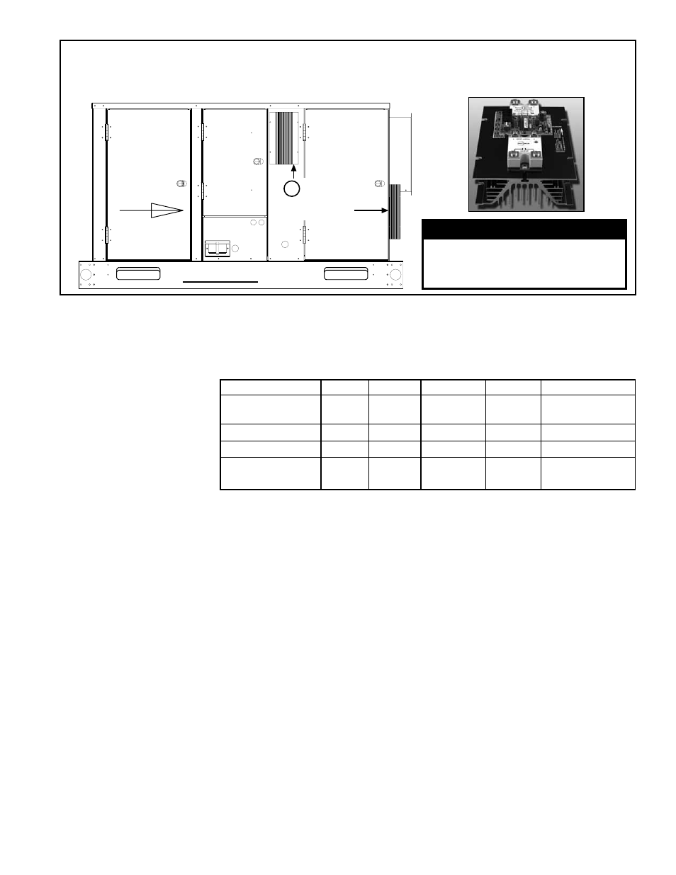
Side View - PEH
Airflow
SCR Control
and Heatsink
Locations
51
Blower
Electrical
Electric
Heat
Section
DANGER
High voltages are present on
the terminals of the SCR power
controller(s).
SCR Power Control and Heatsink
in Option D12D (one or two
required depending on amps)
FIGURE 1C - Locations of the SCR Power Controls
with Heatsinks used on Model REH and PEH units
with Modulating Heat Control Option D12D