0 maintenance procedures (cont’d) – Reznor PDH Operation Manual PreevA User Manual
Page 16
Form O-PreevA, Page 16
3.4 Gas-Fired Heat
Section - PDH,
SDH, RDH, RHH,
& SHH (cont’d)
3.4.5 Gas Train
Components (cont’d)
Manifold Pressures for Option AG58 or D12G Gas Modulation System
(cont’d)
To adjust AG58 or D12G gas modulation ball valve on Model SHH, RHH, or RDH (Sizes 175-400),
follow instructions below:
1. Checking modulation requires a 0-10 DC volt generator and a manometer capable of reading to 0.10" w.c. .
a) Connect the manometer to the manifold pressure tap next to the transducer (
FIGURE 4, page 14).
b) Connect the leads from the 0-10 DC volt generator to the “analog + and _” screw terminals on the control board
after marking, removing, and capping the wires already at those terminals.
c) Initiate a call for heat with either the thermostat (Option CL36, modulating wall heating/cooling Model T7350M)
if equipped with Option AG58 or the FX06 controller (refer to Form CP-PREEVA-D12B/D/E/F/G) if equipped
with Option D12G.
2.
Run the unit at 100% by setting the DC voltage at 10 volts; measure the manifold pressure. If the manifold
pressure matches the High Setting value in the chart (above), continue to Step No. 3. If the manifold pressure
does not match the value in the chart and the ball valve is fully or close to fully open, adjust the pressure screw(s)
on the Honeywell valve (See
FIGURE 5 and the CAUTION on page 15) until the pressure matches the chart.
When the manifold pressure measured at the manometer matches the pressure listed in the chart, make a note
for future reference of the position of the ball valve stem in relation to the dash marks on the actuator.
3.
Reduce the DC volts to 2 volts and allow the ball valve to go to its lowest setting. Check the manifold pressure
on the manometer. If the manifold pressure matches the Low Setting value in the chart, skip to Step No. 4. If the
manifold pressure does not match the low (0%) value on the chart, the ball valve will need to be adjusted. Follow
these steps:
a) While the unit is still firing at 0% modulation, remove the ball valve actuator. To do this, locate the screw on
the rear of the actuator and remove it. Loosen the actuator set screw (See
FIGURE 6, page 15), and carefully
remove the actuator by lifting it straight up. Do not disconnect any wires.
b) Using adjustable pliers, slowly turn the ball valve stem until the manifold pressure on the manometer matches
the low setting on the chart.
Important NOTE: If the valve is adjusted too far closed and the flame goes out, let the unit recycle and then
manually open the ball valve to the 100% open position noted in Step No. 2. When the unit is firing at full fire,
re-attach the actuator to the ball valve, and repeat the procedure beginning with Step No. 2.
c) When the manometer readings match the values in the chart and before re-installing the actuator, the burr left
on the ball valve stem from the previous set screw setting needs to be removed. Either lightly file the burr on
the valve stem to prevent the set screw from returning to the previous position or remove the valve stem, rotate
it 180° so that the set screw contacts the opposite side of the stem, and re-install the valve stem.
d) Re-install the actuator making sure it is level on the ball valve mounting plate.
e) Re-check the setting by going to full fire (Set DC volts to 10 volts) and then returning to 2 volts. Measure the
manifold pressure. The adjusted gas pressure should be close to the value on the chart. If not, repeat the
procedure.
4.
When the settings are in agreement with the chart and testing is complete, remove the manometer. Remove the
wire leads from the DC volt generator and replace the thermostat or FX06 control wiring.
3.0 Maintenance
Procedures
(cont’d)
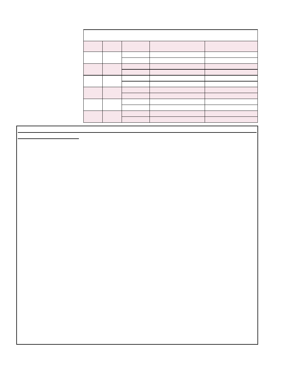
Manifold Pressure (" w.c.) Measured at the Pressure Tap by the Gas
Transducer - Gas Control Option AG58 or D12G (cont’d)
RDH
Size
RHH/
SHH
Gas
Type
High Setting
100% on ModHeat
Low Setting
0% on ModHeat
200
180
Natural
3.4
0.15
Propane
10.0
0.25
225
--
Natural
3.4
0.15
Propane
10.0
0.30
250
--
Natural
3.4
0.15
Propane
10.0
0.25
300
260
Natural
3.4
0.15
Propane
10.0
0.30
350
--
Natural
3.4
0.15
Propane
10.0
0.25
400A
350
Natural
3.4
0.15
Propane
10.0
0.25