0 maintenance procedures (cont’d), Warning, 8 optional evaporative cooling module (cont’d) – Reznor PDH Operation Manual PreevA User Manual
Page 28
Form O-PreevA, Page 28
3.0 Maintenance
Procedures
(cont’d)
WARNING
Disconnect all power to the unit before doing any maintenance.
Failure to do so can cause electrical shock, personal injury, or
death.
Pre-Filters and Media - Over time, excessive amounts of dirt or mineral deposits may
begin to build up on the pre-filters and media. Annually, wash scale and dirt from the
metal pre-filters (pre-filters are optional and may not be on your cooler) and the enter-
ing surface of the media.
Remove the pre-filters (remove the door and slide out). Clean the metal pre-filters with
soap and water and rinse thoroughly.
Clean the entering side of the media using a garden hose, mild soap, and a
soft
bristled brush. When the media becomes too clogged with mineral deposits and dirt
that it cannot be cleaned, the pads should be replaced. The average pad life expec-
tancy is approximately three cooling seasons. Order replacement media pads from
your distributor.
Media - 12" Glacier-Cor® or Glasdek®
PDH/SDH/RDH
PEH/REH
PXH/RXH RHH/SHH
(Qty) Dimensions - inches
(Qty) Dimensions - mm
75, 100
10A, 20A, 40A
000A
N/A
(2) 27-3/32 x 12; (1) 27-3/32 x 7-1/2
(2) 688 x 305; (1) 688 x 191
125, 150
15B, 30B, 60B
000B
N/A
(2) 27-3/32 x 12; (1) 27-3/32 x 5-1/2
(2) 688 x 305; (1) 688 x 140
175, 200, 225
N/A
000C
130 ,180 (2) 36 x 12; (1) 36 x 7-1/2
(2) 914 x 305; (1) 914 x 191
250, 300
30D, 60D, 90D, 120D
000D
260
(3) 36 x 12; (1) 36 x 11-3/4
(3) 914 x 305; (1) 914 x 298
350, 400A
40E, 80E, 120E
000E
350
(4) 36 x 12; (1) 36 x 7-3/4
(4) 914 x 305; (1) 914 x 197
Optional Pre-Filters for Evaporative Cooling Module - 1" or 2" Aluminum Filters
PDH/SDH/RDH
PEH/REH
PXH/RXH RHH/SHH
(Qty) Dimensions - inches
(Qty) Dimensions - mm
Top Row
Bottom Row
Top Row
Bottom Row
75, 100
10A, 20A, 40A
000A
N/A
(2) 16 x 12
(2) 16 x 16
(2) 406 x 305
(2) 406 x 406
125*, 150*
15B*, 30B*, 60B*
000B*
N/A
(1) 16 x 12;
(1) 26 x 12
(1) 16 x 16;
(1) 16 x 25
(2) 406 x 305;
(1) 660 x 305
(1) 406 x 406;
(1) 406 x 635
175, 200, 225
N/A
000C
130 ,180 (2) 16 x 12
(2) 16 x 16
(2) 406 x 305
(2) 406 x 406
250*, 300*
30D*, 60D*, 90D*, 120D*
000D
260
(3) 16 x 12
(3) 16 x 25
(3) 406 x 305
(3) 406 x 635
350*, 400A*
40E*, 80E*, 120E*
000E
350
(1) 16 x 12;
(2) 20 x 12
(1) 16 x 25;
(2) 20 x 25
(1) 406 x 305;
(2) 508 x 305
(1) 406 x 635;
(2) 508 x 635
NOTE: Glacier-Cor® and Glasdek® are trademarks of Munters Corporation.
* These sizes require a filter stop gasket in each row.
Qty and Sizes of
Evaporative Cooling
Media and Pre-Filters
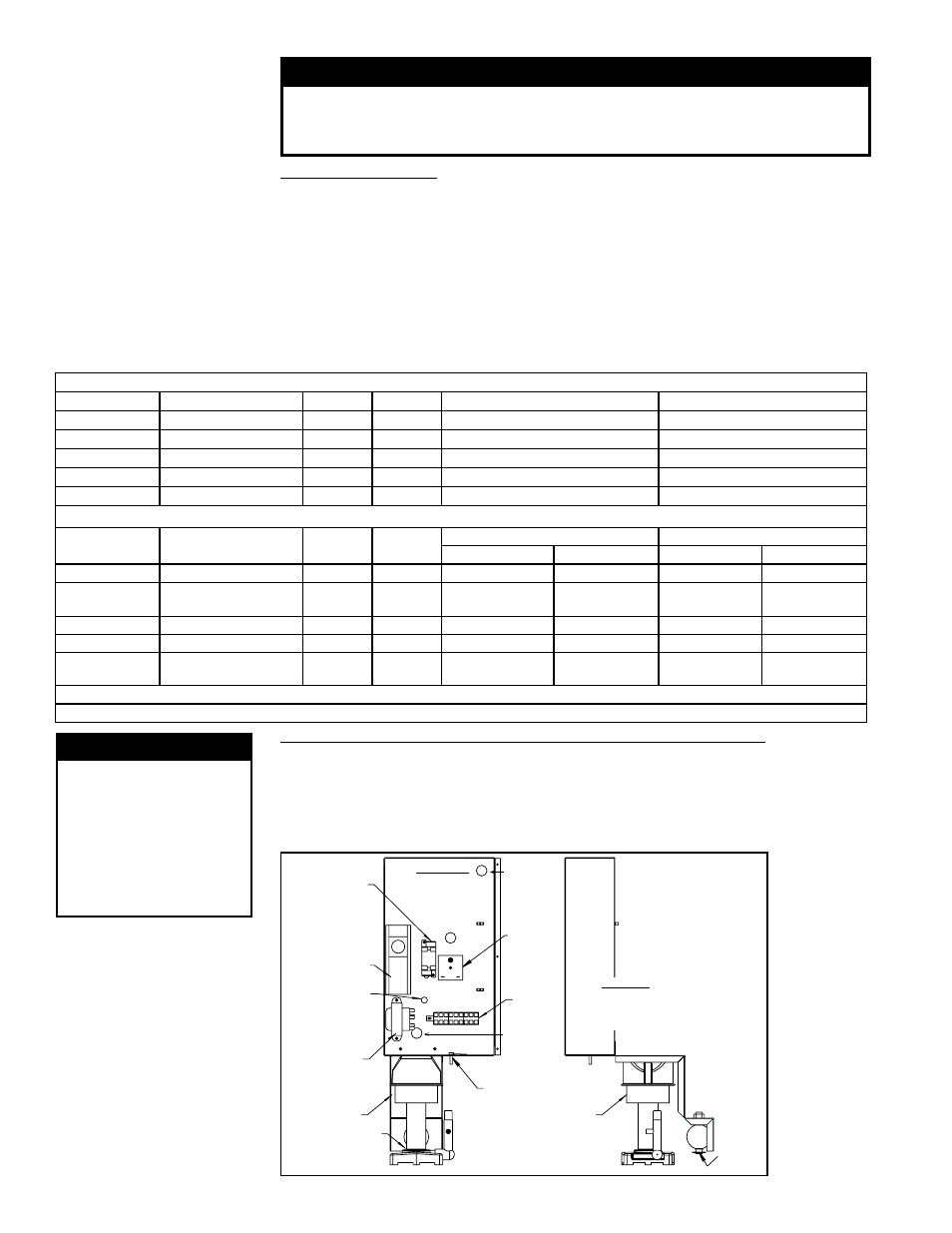
FIGURE 9 - Remove
electrical box/pump/
float switch as an
assembly. Shown here
with Option CT6, Freeze
Protection controls.
Relay Socket
and Relay
(with Option
CT6, Freeze
Protection, only)
Temperature
Controller
(with Option
CT6 only)
Temperature
Controller
Probe Port
with Option
CT6 (hole plug
without CT6)
Transformer
(208v/1or3ph
only)
Ground Screw
and Lead
Terminal
Block
Time Delay
Relay
(with Option
CT6 only)
Entrance for
power and
control wires
from unit
Front View
Electrical Box,
Float Switch,
and Pump
Assembly
Side View
Electrical Box,
Float Switch,
and Pump
Assembly
Pump
and
Motor
Float
Switch
Entrance for
pump and
switch wires
Pump and
Motor
Float
Switch
Water Pump and Inlet Basket Screen on a Float and Pump System - Annually, the
pump and inlet basket screen should be removed, disassembled, and cleaned.
3.8 Optional
Evaporative Cooling
Module (cont’d)
WARNING
Do not expose
pump motor or
any part of the
electrical box to
water. Evaporative
cooling pump is
NOT submersible.
1. Disconnect the power supply to the unit.
2. Remove the door panel. Disconnect the two-line voltage power supply wires from
the terminal block inside the electrical box. See
FIGURE 9.
3. Disconnect the water feed line hose from the upstream side of the ball valve.