Reznor PDH Operation Manual PreevA User Manual
Page 17
Form O-PreevA, P/N 234661R8, Page 17
3.4.6 Venter Motor,
Wheel, and Pressure
Sensing Tap
Remove dirt and grease from the motor casing, the venter housing, pressure sensing
tap, and the venter wheel. Venter motor bearings are permanently lubricated.
Follow these instructions for replacement of the venter motor and wheel assembly.
Keep all hardware removed to be used in re-assembling and installing the replacement
parts.
1. Turn off the gas and disconnect the electric power.
2. Open the burner/control compartment door panel.
3. Disconnect the two or three venter motor wires at the DSI control or the venter
speed control board, capacitor wires at the capacitor (if applicable), and ground
screw (located on the control panel).
4. Holding the venter motor, remove the three, four, or six screws that attach the
venter motor mounting plate to the venter housing. Remove the motor and wheel
assembly from the heater.
5. Re-assemble with the replacement venter motor and wheel assembly. See
FIGURE 7, for correct spacing. If there is a motor plate gasket, check it. If the
gasket is damaged, replace it.
Venter Motor and
Wheel Assembly
Replacement
Instructions
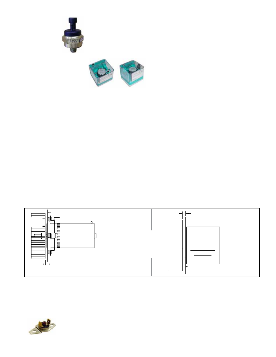
Gas Manifold
Transducer -
part of Gas
Control
Options AG58
or D12G
Location: See FIGURE 4, page 14 .
Function: With Option AG58 or D12G gas control, the transducer reads the manifold
pressure and sets the venter motor speed to precisely match the designed combustion
settings.
Service: If the transducer needs to be replaced, use only a factory-authorized replace-
ment part designed for the purpose.
Optional Gas Pressure
Switches
Location: Low pressure switch is at the entrance to
the gas train. The high pressure switch is at the burner
end.
Function: To monitor gas pressure and shut down the
heat section if gas pressure becomes too low or too
high. The low pressure switch is an auto reset type and
is set at 50% of the maximum manifold pressure. The high pressure switch requires
manual reset and is set at 125% of manifold pressure.
Service: There are no replaceable parts and the settings are non-adjustable. If replace-
ment is required, use identical factory-authorized safety switches.
FIGURE 7 - Venter
Wheel Position on Shaft
Motor plate to wheel
5/16 (8mm) inside - PDH/SDH/RDH 75-150
7/16 (11mm) inside - PDH/SDH/RDH 175-400A
Venter Motor
Models PDH,
SDH, and RDH
Motor Plate (PDH/SDH/RDH 175-400A have a motor
plate gasket,
P/N 201472.)
Motor Mounting Plate
Venter
Wheel
NOTE: Manufacturer
recommends replacing
venter motor capacitor when
replacing venter motor.
Motor plate to wheel
RHH/SHH 130 - 5/16” (7.9mm);
RHH/SHH 180, 260, 350 - 1/2” (12.7mm)
Venter
Motor
Models RHH
and SHH
Venter Wheel
Motor Plate (and Motor
Plate Gasket, P/N 221163
6. Follow the wiring diagram to connect the venter wires.
7. Close the door panel. Restore power to the heater and turn on the gas. Light,
following the instructions on the lighting instruction plate. Check for proper
operation.
Vent Temperature Limit
Switch - RHH & SHH
Function: The vent temperature limit switch is a manual reset, temperature activated
safety control. Its purpose is to prevent the vent gas temperature from exceeding a
temperature that will harm the PVC vent pipe. Setpoint is 145°F.
Service: If the vent temperature limit switch is activated, identify and correct the cause
before resetting the switch. The switch could be activated by one or more of the fol-
lowing:
P/N 221158