3 electrical compartment, 0 maintenance procedures (cont’d) – Reznor PDH Operation Manual PreevA User Manual
Page 8
Form O-PreevA, Page 8
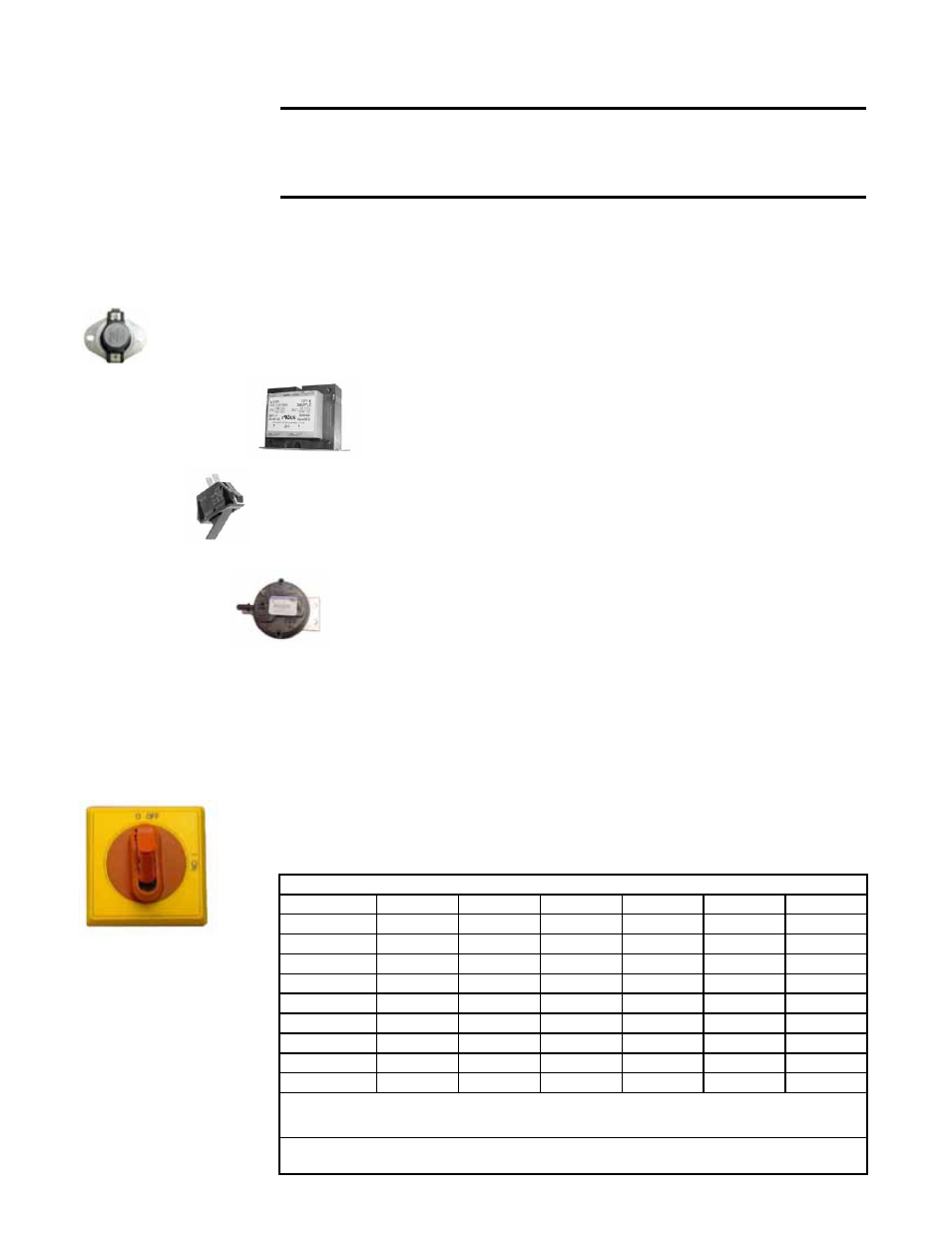
3.3.5 Built-in On/
Off Control Switch,
Option BA6
Function: Optional lockable service control switch.
Service: If it is determined that the control switch needs to be replaced, use only the
factory-authorized replacement part that is designed for the heater.
Location: Switch is conveniently mounted below the electrical compartment on the
outside of the unit.
Application: The switch on Models PDH, SDH, SHH, PXH, RHH, RDH, and RXH
is
P/N 205908. The switch used on Models PEH and REH differs by size; see chart
below.
3.3.3 Door
Switch -
Models
SDH, SHH
Function: Prevents unit from operating when the heat section door is open.
Service: If it is determined that the door switch needs replacing, use only a
factory-authorized replacement part that is designed for the heater.
Location: Models SDH/SHH heat section.
P/N
217262
3.0 Maintenance
Procedures
(cont’d)
OPTION BA6 REQUIRED DISCONNECT SIZE for Electric Heat MODELS PEH and REH (AMPS)
208/1/60
240/1/60
208/3/60
240/3/60
460/3/60
575/3/60
10 KW
80
100
N/A
N/A
N/A
N/A
15 KW
100
125
N/A
N/A
N/A
N/A
20 KW
125
200
80
80
60
60
30 KW
200
200
100
125
60
60
40 KW
N/A
N/A
125
200
80
60
60 KW
N/A
N/A
200
200
100
100
80 KW
N/A
N/A
200
250
125
125
90 KW
N/A
N/A
250
N/A
200
125
120 KW
N/A
N/A
N/A
N/A
200
200
Available Disconnect Switch Sizes (Amps): 60 (P/N 205906), 80 (P/N 205907),
100 (P/N 205908), 125 (P/N 207678), 200 (P/N 207679) and 250 (P/N 222422)
Note: These ratings are based upon 115% of the total FLA for heat modules plus
motor.
3.3.1 Reverse Flow
Limit Control - PDH,
SDH, RDH, RHH, SHH
Function: The reverse flow limit control is an automatically reset, temperature acti-
vated safety control.
Service: If it is determined that the reverse flow limit control needs replacing, use only
a factory-authorized replacement part that is designed for the size of heater.
Location: PDH/SDH/RDH 75-150 in the blower section. PDH/SDH/RDH 175-400 and
all RHH/SHH in the heat section. For approximate location, see
FIGURE 1A, page 5.
3.3.2 Transformer
Service: Use a voltmeter to verify that there are 24 volts output from a
transformer. If the transformer is not functioning, it must be replaced. Use
a replacement transformer identical to the factory-installed model.
Location: See FIGURE 1A, page 5, or 1B, page 6, for location.
P/N
211754
3.3 Electrical Compartment
Check the wiring and connections. Replace any wiring that is deteriorated.
CAUTION: If any of the original wire as supplied with the appliance
must be replaced, it must be replaced with wiring material having a
temperature rating of at least 105°C, except for sensor lead wires which
must be 150°C. See Hazard Levels, page 2.
Controls identified below apply to all models unless specifically listed.
3.3.4 Condensate
Pressure Switch
- Models RHH &
SHH
Function: If the condensate drain is blocked causing the sensing pressure to
be outside the switch setpoint, the pressure switch will shutoff the gas valve.
The gas valve will remain off until the problem is corrected.
Service: If it is determined that the condensate pressure switch needs replac-
ing, use only a factory-authorized replacement part that is designed for the
heater.
Location: See FIGURE 1A, page 5, Item 22, for location.
P/N 217085