Warning, 0 maintenance procedures (cont’d) – Reznor PDH Operation Manual PreevA User Manual
Page 14
Form O-PreevA, Page 14
3.4 Gas-Fired Heat
Section - PDH,
SDH, RDH, RHH,
& SHH (cont’d)
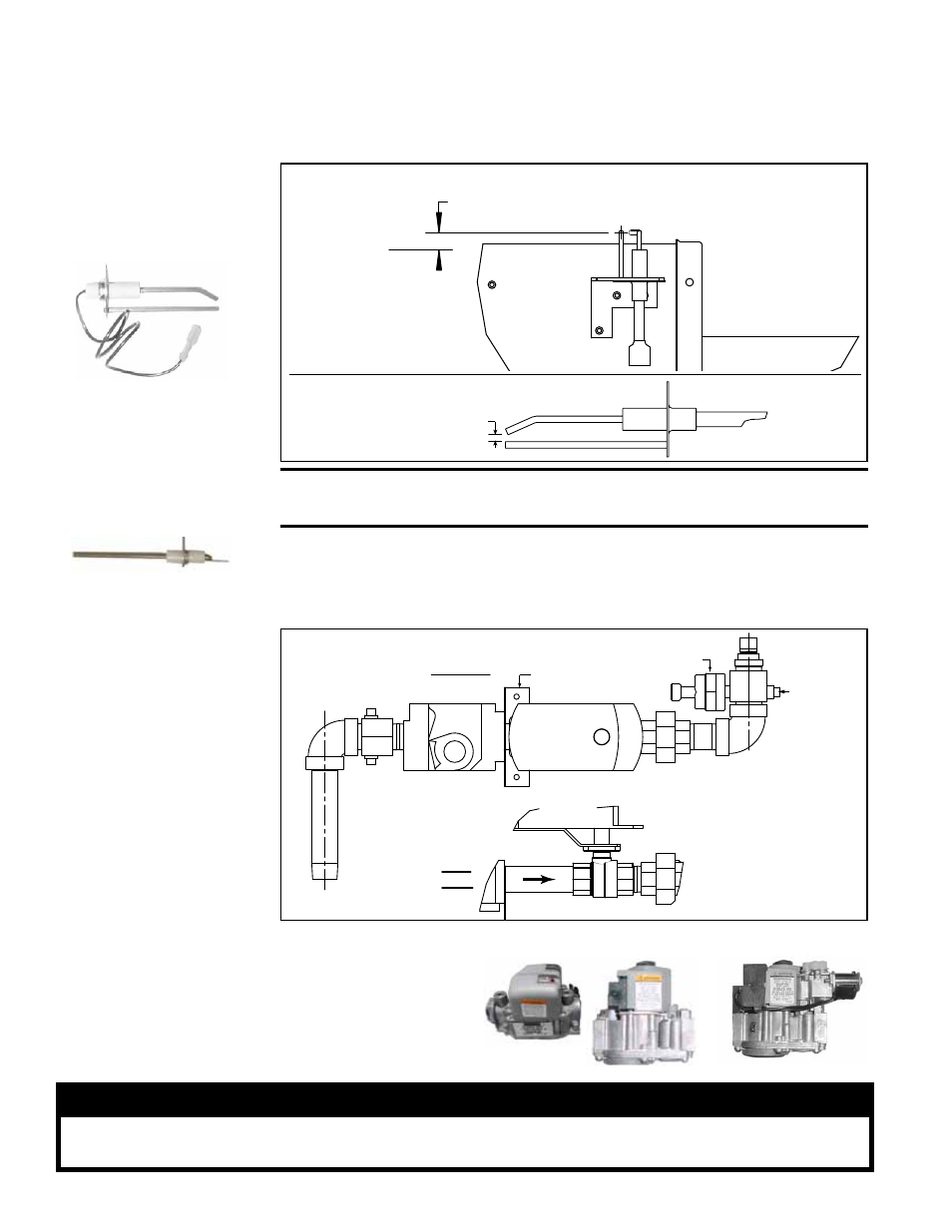
3.4.4 Ignition System
Ignitor - Locate the ignitor. Disconnect the wire; remove the screw and the ignitor.
Clean the ignitor assembly with an emery cloth.
Ignitor, P/N 209339
1/8 inch
(3.2mm)
FIGURE 3 - Ignitor Location and Spark Gap
CAUTION: Due to high voltage on the spark wire and electrode,
do not touch when energized. See Hazard Levels, page 2.
Flame Sensor,
P/N 209973
Flame Sensor - Locate the flame sensor. Disconnect the wire; remove the screw and
the flame sensor. Clean with an emery cloth.
Spark gap must be maintained to 1/8”.
IMPORTANT: When re-assembling, the brown
ground wire must remain attached to the ignitor.
Spark Gap
measurement
.436 (centerline of ignitor to top of ribbon)
Ignitor
Location
3.4.5 Gas Train
Components
Top View
Side
View
Ball Valve
Actuator
Ball Valve
Actuator
Combination
Gas Valve
Pressure
Tranducer
Ball Valve
Gas Valve
Bracket
Orifice
Manifold
Pressure
Tap
FIGURE 4 - Gas Train
Component Locations
for a Burner with 8:1
turndown (Modulating
Gas Control Option
AG58 or D12G) - applies
only to Model RDH
Sizes 175-400, Model
RHH, and Model SHH
The gas train components differ depending on the gas control option selected. See the
location of gas train components in
FIGURE 1A, page 5, and below in FIGURE 4.
Carefully remove external
dirt accumulation and check
wiring connections.
The combination gas valve
must be checked annually
to ensure that the valve is
shutting off gas flow com-
pletely.
Single-Stage Gas Valves
Two-Stage Gas Valve
WARNING
The operating valve is the prime safety shutoff. All gas supply lines must be free of
dirt or scale before connecting to the unit to ensure positive closure.
Single-Stage and
Two-Stage Gas
Valves
3.0 Maintenance
Procedures
(cont’d)