With option hw2 hot water heat module, 0 troubleshooting -37, Circuit board) - pdh, sdh, shh, rhh, and rdh – Reznor PDH Operation Manual PreevA User Manual
Page 30: 0 troubleshooting, 0 maintenance procedures (cont’d), Lights
Form O-PreevA, Page 30
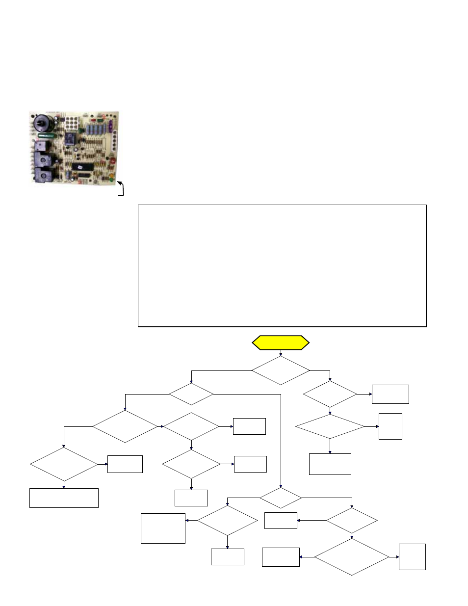
DSI Integrated Control Module (Circuit Board)
Trial Troubleshooting Flowchart - All SDH, PDH,
RDH, SHH, RHH (does not apply when
equipped with Gas Control
Option AG58 or D12G)
4.0 Troubleshooting
The integrated circuit board monitors the operation of the heater and includes two
LED signal lights that indicate normal operation and various abnormal conditions. If
the heater fails to operate properly, check this signal to determine the cause and/or to
eliminate certain causes. LED is visible through viewport on Models SDH and SHH.
Open the door panel on Models PDH and RDH.
Do not attempt to repair the DSI integrated control module; the only field replaceable
component is the fuse.
4.1 Check the Lights on the DSI Integrated Control Module
(Circuit Board) - PDH, SDH, SHH, RHH, and RDH
NOTE: Applies to all models listed and all sizes except Model RDH 175-400A Model
RHH, and Model SHH
with Gas Control Option AG58 or D12G (See Paragraph 4.2.)
IMPORTANT: When using
a multimeter to troubleshoot
the 24 volt circuit, place the
meter’s test leads into the 5
or 9 pin connectors located
on the ignition control. Do
not remove connectors or
terminals from the electrical
components. Doing so can
result in misinterpreted
readings due to the ignition
control board’s fault mode
monitoring circuits.
Control Status - Green LED Codes
Steady ON .... Normal Operation, No call for heat
Fast Flash ..... Normal Operation, Call for heat
1 Flash .......... System Lockout, Failed to detect or sustain flame
2 Flashes ...... Pressure Switch Did Not Close within 30 Seconds of Venter Motor
3 Flashes ...... High Limit Switch Open
4 Flashes ...... Pressure switch is closed before venter motor is energized
Steady OFF .. Blown Fuse, No Power, or Defective Board
Flame Status - Yellow LED Codes
Steady ON .... Flame is sensed
Slow Flash .... Weak flame (current below 1.0 microamps ±50%)
Fast Flash ..... Undesired Flame (valve open and no call for heat)
Trial for Ignition
Call for Heat
Is there a
spark across gap at
ignitor?
Does gas
ignite?
Is there minimum
flame current at the
flame sensor?
Is there
minimum flame current
at the control
module?
Replace control
module.
Check connections to flame
sensor and/or moisture in the
burner assembly.
Is the flame
sensor
corroded?
Clean flame
sensor.
Is the sensor
located in flame
correctly?
Replace flame
sesnsor.
Reposition
flame sensor.
Is gas
flowing?
Is the ignitor
position correct in the
gas flow?
Check gas pressure
and supply voltage.
If either are low,
correct and repeat
startup.
Reposition
spark ignitor.
Is there
24VAC at the gas
valve?
Is there 24VAC
from gas valve output on
control module to
chassis?
Check wiring and
connections to
gas valve.
Replace
ignition
control
module.
Replace gas
valve.
Is there
spark voltage at
control?
Check high
voltage wire
continuity.
Is there 24V P1-2
to power control?
Replace
control
module.
Check wiring
and/or 24VAC
transformer output.
YES
NO
YES
NO
YES
NO
YES
NO
YES
NO
YES
NO
YES
NO
YES
NO
NO
YES
YES
NO
YES
NO
YES
NO
Lights
3.0 Maintenance
Procedures
(cont’d)
3.9 Hot Water Heat - applies only to Model PXH or Model RXH
with Option HW2 Hot Water Heat Module
The closed hot water system requires a proper water treatment program with regular
water analyses, adequate regulated drains, and periodic inspection. Check for dirt or
debris that could inhibit airflow. Clean with low pressure air blower or water. Follow the
coil and control manufacturer’s instructions for maintenance and service.