6 dampers and controls – Reznor PDH Operation Manual PreevA User Manual
Page 19
Form O-PreevA, P/N 234661R8, Page 19
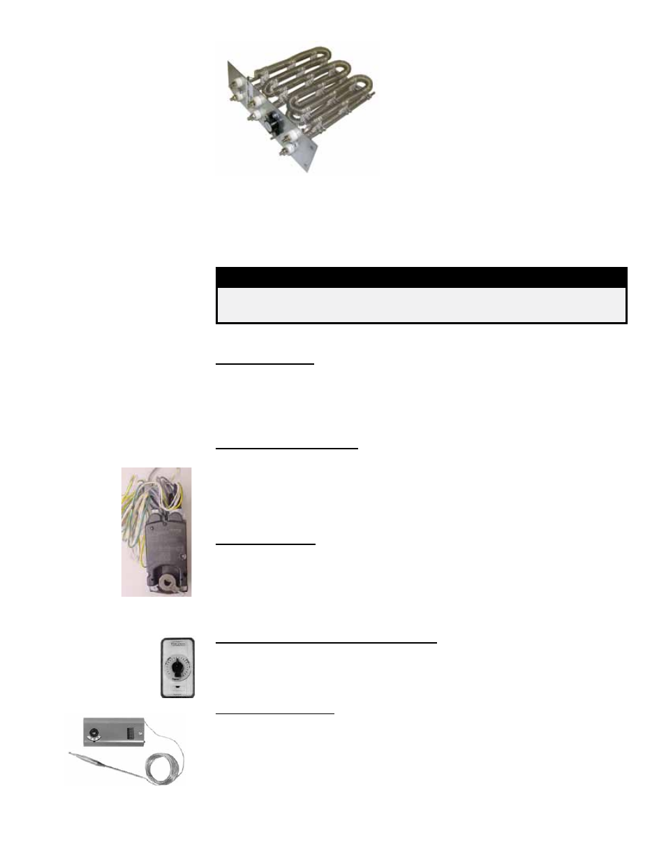
3.5.1 Electric Heating
Elements
Service: Check the heating elements at the
beginning of the heating season. Carefully clean
all dust and dirt from the heating elements using
a brush or steel wool. With a vacuum or air hose,
clean the inside of the cabinet especially the bot-
tom and sides where dirt and dust will accumu-
late.
If a replacement is needed, order a complete
heat section assembly (5kw single phase or 10kw
three phase).
Single Heating Element
(Each heat section includes
an assembly of single
elements.)
Location: See the control location illustration in FIGURE 1B and 1C, pages 6 and 7.
Service: The electric heat section has a transformer, relay, digital controller, contac-
tors, fuses, and a distribution block.
Quantities and types of fuses and contactors depend on the size of unit.
If the electric heat section has SCR control (Option D12D), the controller(s) with heat-
sink are positioned as shown in
FIGURE 1C.
DANGER
High voltages are present on the terminals of the SCR power
controller(s).
If replacements are required, check with your distributor and use only factory-autho-
rized parts.
3.6 Dampers and
Controls
Reference NOTE: Codes for
electrical options are listed
on the wiring diagram.
Inlet Air Dampers
Location: Dampers and damper motors are located in either the blower section (Option
AR8) or the optional mixing box (GE Options).
Function: Dampers operate in response to the control selected. Damper controls are
shown below.
Service: Clean dampers and controls of dust and dirt.
2-Position Damper Motor (Options AR8 and GE 3, 6, 7)
Function: The 2-position damper motor opens and closes the dampers in response to
unit operation, a system switch, or a field-supplied time clock.
Motor closes dampers on heater shutdown.
Service: There is no service required on this motor other than external cleaning. If
the motor needs replaced, replace with an identical damper motor or damper motor
replacement kit.
Modulating Motor (Options GE 4, 8, 10, 11, 12, 13, 14, 15, 16, 21, 22)
Function: The modulating damper motor actuates the dampers in response to dis-
charge air temperature, building pressure, or DDC control. Some options have damper
“stops” or warmup (or cooldown) delay based on return air temperature. Motor closes
dampers on heater shutdown.
Service: There is no service required on this motor other than external cleaning. If the
motor needs replaced, replace with an identical damper motor.
Potentiometer (adjustable damper dial) (Options GE 4, 8, 10, 14)
Function: The potentiometer is a manually set switch used with modulating dampers
to set a minimum outside air damper opening. Depending on the option selected, it is
either mounted in the mixing box or remotely located.
Service: If the potentiometer needs replaced, replace it with an identical switch.
Damper
Motor
Potentiometer,
P/N 16110
Return Air Controller (Options GE 7, 13, 14)
Function: The return air controller senses the temperature of the incoming return air.
On a two-position outside air damper system, it activates the motor to open and close
the outside air damper. On a modulating system, the return air controller maintains
100% return air until the set temperature is reached at which point the mixed air con-
troller (with or without potentiometer) controls the dampers based on the mixed air
control setting. When in the heating mode, the temperature of the “mixed” return and
outside air entering the heater must always be 35°F or above.
Service: If the controller needs replaced, replace it with an identical control.
Return Air Controller,
P/N 126170