5 electric heat section - models peh, reh, 0 maintenance procedures (cont’d), 7 combustion air pressure switch – Reznor PDH Operation Manual PreevA User Manual
Page 18: 8 high temperature limit control, 9 vent or vent/ combustion air system
Form O-PreevA, Page 18
3.4 Gas-Fired Heat
Section - PDH,
SDH, RDH, SHH
(cont’d)
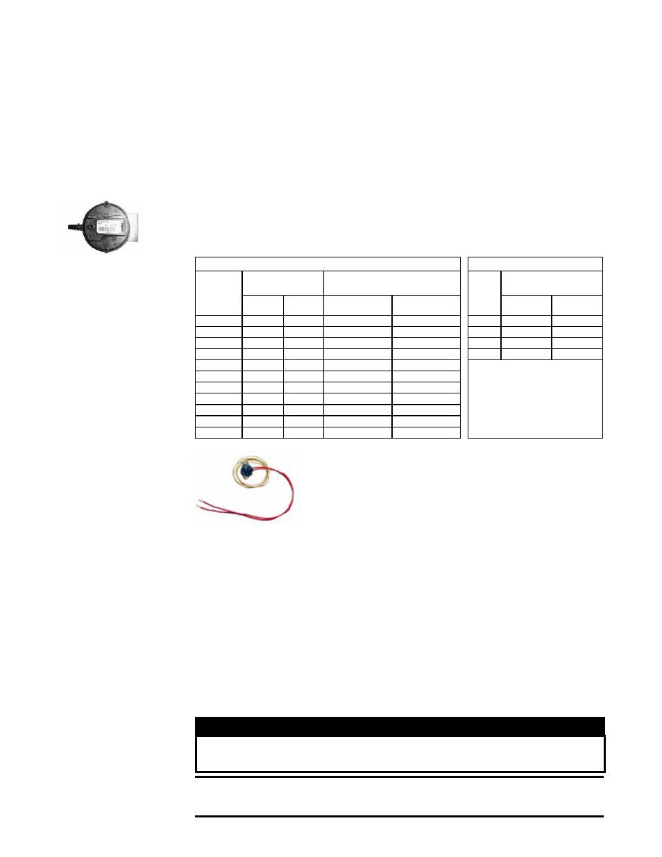
3.4.7 Combustion Air
Pressure Switch
Function: Monitors flow of combustion air.
Service: If it is determined that the pressure switch needs replacing, use only the
factory-authorized replacement part that is designed for the model and size of heater
being serviced. Two-stage units with a two-speed venter and units with electronic mod-
ulation have two pressure switches.
NOTE: A single-stage or two-stage unit operating
above 6000 ft elevation requires a high altitude high speed pressure switch.
Location: See FIGURE 1A, page 5, for location.
3.4.8 High
Temperature Limit
Control
Function: The limit control is an automatically reset, tempera-
ture activated safety control with a capillary sensor. Sensor is
extended across the heater discharge.
Service: If it is determined that the limit control needs replac-
ing, use only a factory-authorized replacement part that is
designed for the size of heater.
Location: For switch location, see FIGURE 1A, page 5.
Sizes 75-150,
P/N 210854
Sizes 175-225,
P/N 210855
Sizes 250-400,
P/N 211066
3.4.9 Vent or Vent/
Combustion Air
System
Check the complete system at least once a year. Inspection should include all joints,
seams, concentric adapter box (Model SDH), combustion air inlet opening, and the
vent terminal cap. Clean openings. Replace any defective parts. Refer to the venting
manual for requirements.
On a Model SHH, clean the vent condensate drain. After cleaning, fill the trap with
water.
3.4.6 Venter Motor, Wheel, and Pressure Sensing Tap (cont’d)
3.0 Maintenance
Procedures
(cont’d)
P/N’s & Settings - Models SDH, PDH, RDH
P/N’s & Settings - RHH & SHH
SDH, PDH,
RDH
Size
High Speed (applies
to all gas controls)
Low Speed (applies only to units with
gas controls using a 2-speed venter)
RHH/
SHH
Size
High Speed (applies to all
gas controls)
Switch
P/N
Setting
(" w.c.)
Switch P/N
Setting
(" w.c.)
Switch
P/N
Setting
(" w.c.)
75
197030
0.4
205442
0.2
130
201161
1.3
100
197030
0.4
205444
0.3
180
201161
1.3
125
196388
0.5
205444
0.3
260
201159
1.4
150
197028
0.7
205444
0.3
350
221228
2.3
175
201158
1.1
197030
0.4
200
201158
1.1
197030
0.4
225
201158
1.1
197030
0.4
250
201158
1.1
197030
0.4
300
201158
1.1
197030
0.4
350
201158
1.1
197030
0.4
400A
201158
1.1
197030
0.4
At the beginning of the cooling season or more often if needed, clean the heat section
condensate drain(s). (Models PDH, SDH, and RDH will have none or one. Model SHH
will have one or two.) Before starting the unit, fill traps with water to ensure proper
operation. If condensate drain is not needed in the winter, drain the trap before heating
season. If condensate drain is used in below freezing temperature, provide a means
of freeze protection.
3.4.10 Heat Section
Condensate Drain(s)
3.5 Electric Heat
Section - Models
PEH, REH
WARNING
Turn off the power locking the disconnect switch. Allow the
heating elements to cool.
CAUTION: Wearing eye protection is recommended when cleaning
the heating elements and cabinet.
Vent Temperature Limit Switch (cont’d) - Models RHH & SHH
•
Manifold gas pressure is too high
•
The heat content of the fuel is too high
•
Reduced circulating airflow due to dirty and/or plugged air moving components
•
Excess dirt on the heat exchangers
•
Failed heat exchanger (s)
Location: On the side of the venter housing.