Reznor PDH Operation Manual PreevA User Manual
Page 13
Form O-PreevA, P/N 234661R8, Page 13
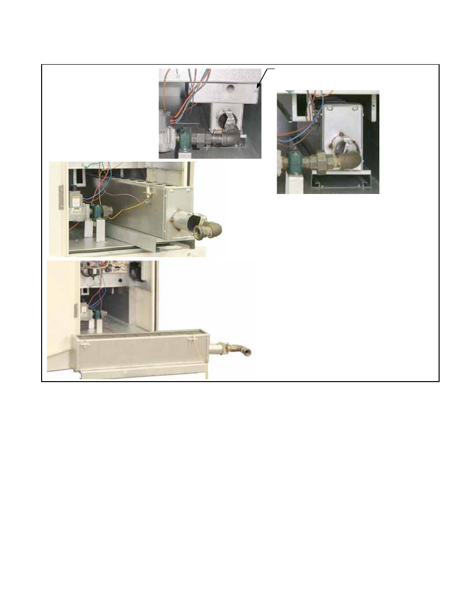
FIGURE 2 - Burner
assembly is designed
to slide out of the
cabinet.
Loosen screw to remove burner shield
end. Screw will stay attached to shield.
Disconnect the gas supply at the union closest to
the burner.
Pull the burner forward.
To remove the burner, disconnect the
flame sensor wires and the ignitor. Pull the
burner until it slides off the support rails.
Clean all foreign material from the burner and venturi. After the burner is thoroughly
clean, replace the end cap making certain that it is tight against the burner housing.
NOTE: If any of the burner components are damaged or deteriorated, replace the
burner assembly.
Inspect the Lower
Portion of the Heat
Exchanger (with burner
removed)
Instructions to Re-Install the Burner (See FIGURE 2.)
1. Position the burner on the rails and slide the burner assembly part way into the
cabinet. Re-attach the sensor and ignitor wires. Slide the burner into “working”
position.
2. Re-attach the gas train. Do not allow the portion of the gas train attached to the
venturi tube to turn. Be sure the burner is positioned correctly. Check to be sure
that the orifice is secure and positioned correctly.
3. Re-attach the burner shield end.
4. Close and latch the burner cabinet door.
5. Turn on the electric and the gas. Check for proper operation.
3.4.3 Burner Orifice
The burner orifice usually only needs to be replaced when installing a gas conversion
kit. If ordering a replacement orifice only, give BTUH content and specific gravity of
gas, as well as the model and serial number of the unit. When removing or replacing
the burner orifice be careful not to damage the venturi tube and/or the bracket.
At the burner flame entrance of each tube, shine a bright light into each heat exchanger
section. With the light shining into the heat exchanger, observe the outside for visible
light. Repeat this procedure with each heat exchanger section. If any light is observed,
replace the heat exchanger.