Reznor PDH Operation Manual PreevA User Manual
Page 29
Form O-PreevA, P/N 234661R8, Page 29
Troubleshooting the Operation of an Evaporative Cooling Module
PROBLEM
PROBABLE CAUSE
REMEDY
Pump doesn’t run (pump &
float system) – Unit is calling
for cooling (i.e. console control
switch is in cool or summer
position) and reservoir is full.
1. Electrical connections.
1. Verify all electrical connections. Verify correct voltage at pump terminals in the
junction box. See wiring diagram.
2. Electric float switch..
2. Check position of the actuators on the electric float switch.
3. Dirty pump.
3. Clean pump.
4. Defective pump.
4. Replace pump.
Required water level (3"/76mm)
not being maintained (pump &
float control system).
1. Float valve.
1. Adjust float valve..
2. Optional drain and fill valves.
2. Check valves for proper operation.
3. Drain leaking.
3. Tighten drain fittings.
Water running off of media
pads.
1. Excessive water flow.
1. Adjust ball valve in distribution line.
2. Media pads need cleaned or replaced. 2. Clean or replace media pads.
Water not distributing evenly.
1. Distribution line clogged.
1. Flush distribution line..
2. Holes in distribution line turned.
2. Check position of distribution line. Holes should be spraying upward toward
diffuser. If not positioned with holes toward top, adjust position of distribution line.
3. Pump not running on correct voltage
(pump and float control system).
3. Check voltage at pump terminal in cooling module junction box.
Media pads becoming clogged
and discolored quickly (scale
and salt deposits).
1. Bleedoff line clogged or inadequate
bleedoff (pump and float control system).
1. Clean bleed line. A uniform buildup of minerals on the entering air face of the
media indicates insufficient bleedoff. Increase the rate until the mineral deposits
dissipate.
2. Excessive water flow.
2. Reduce flow by adjusting ball valve in distribution line..
Water blowoff from media pads
or water being pulled from
reservoir.
1. Media pads installed incorrectly.
1. Install media pads with airflow as shown on pads.
2. Water level not 3" (76mm) (pump and
float control system).
2. See second problem listed (Required water level not being maintained).
4. Remove the three sheetmetal screws holding the electrical box to the cooling
module. Remove the electrical box/pump/float switch as an assembly.
5. Remove the mesh screen from around the pump and clean any buildup of debris
and dirt. Carefully remove the base cover plate from the bottom of the pump.
Using a mild soap solution, wash all deposits from the inside of the pump and
remove all debris from the impeller.
6. Reassemble the pump. Replace the parts in exact reverse order, being careful that
everything is returned to its original position.
Water Distribution Line - Annually, the water distribution line should be flushed of
debris and contaminants.
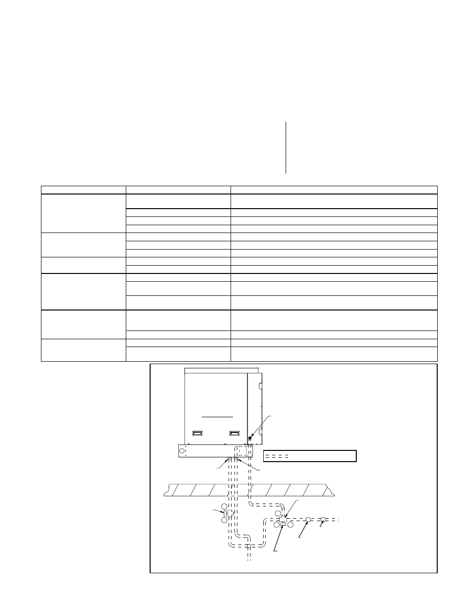
Evaporative
Cooling
Module
(factory attached)
Inlet Water Connection
(1/2 male NPT fitting)
Overflow Fitting
3/4 male NPT tapped
with 1/2 female NPT
Drain Fitting
3/4 male NPT tapped
with 1/2 female NPT
2-Way Solenoid Valve
(normally open)
1/2 female NPT
(A 2-way valve is in
Options CT1, CT2, and CT3.
Option CT6 requires
Option CT1, CT2, or CT3.)
To Drain
3-Way Solenoid Valve (valve is suitable for a maximum
close-off pressure differential of 25 psi and a system static
pressure of 300 psi) - 1/2 NPT, 2-position spring return
(normally closed at B port) (A 3-way valve is in Options CT1, CT2,
CT3, and CT5. Option CT6 requires Option CT1,CT2, or CT3.)
Actuator must be above the valve body
when mounted in horizontal piping.
Roof
Water Inlet
Field-supplied
Service Valve
Field-supplied Pressure
Regulator (if required)
A
A
B
B
C
= Field-installed Water Piping
Left Side View
FIGURE 10 - Water
Connection and Field-
Installed Fill and Drain
Valves for Pump and
Float System and
Freeze Protection Kits
1. Disconnect the power supply to the
unit.
2. Remove the access panel and the
media pads.
3. Remove the water feed line from the
downstream side of the ball valve.
4. Force a fresh water supply through the
water inlet hose to thoroughly flush the
distribution line.
5. Reassemble being careful to install media
with airflow direction as marked on the
media pads.