2 troubleshooting – Reznor LDAP Unit Installation Manual User Manual
Page 41
Form I-LDAP, P/N 207733R6, Page 41
The integrated circuit board monitors the operation of the heater and includes
two LED signal lights that indicate normal operation and various abnormal con-
ditions. If the heater fails to operate properly, check this signal to determine the
cause and/or to eliminate certain causes. See operating sequence in Para-
graph 8.
Do not attempt to repair the DSI integrated control module; the only field
replaceable component is the fuse.
Check the Lights on
the DSI Integrated
Control Module
(Circuit Board)
IMPORTANT: When
using a multimeter to
troubleshoot the 24 volt
circuit, place the meter’s
test leads into the 5 or 9
pin connectors located
on the ignition control.
Do not remove connec-
tors or terminals from the
electrical components.
Doing so can result in
misinterpreted readings
due to the ignition control
board’s fault mode moni-
toring circuits.
10.2 Troubleshooting
DSI Integrated Control
Module (Circuit Board)
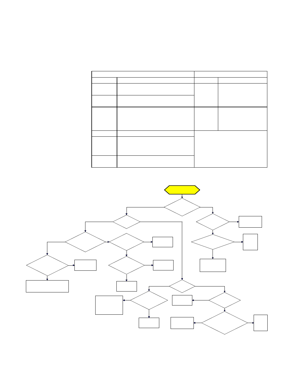
Trial Troubleshooting
Flowchart
Control Status - GREEN LED Codes
Flame Status - YELLOW LED
Steady On Normal Operation - No call for heat. Steady On Flame is sensed.
Fast
Flash
Normal Operation - Call for heat.
Slow
Flash
Weak flame (current
below 1.0 microamps
±50%)
1 Flash System Lockout (failed to detect or
sustain flame)
2 Flash
Main combustion air pressure switch
or heat section pressure switch does
not close with 30 seconds of venter
being energized.
Fast
Flash
Undesired flame
(valve open and no
call for heat).
3 Flash Limit or high limit switch open.
4 Flash
Main combustion air pressure switch
or heat section pressure switch is
closed before venter is energized.
Steady
Off
Blown fuse; No power; or Defective
board
Trial for Ignition
Call for Heat
Is there a
spark across gap at
ignitor?
Does gas
ignite?
Is there minimum
flame current at the
flame sensor?
Is there
minimum flame current
at the control
module?
Replace control
module.
Check connections to flame
sensor and/or moisture in the
burner assembly.
Is the flame
sensor corroded?
Clean flame
sensor.
Is the sensor
located in flame
correctly?
Replace flame
sesnsor.
Reposition
flame sensor.
Is gas
flowing?
Is the ignitor
position correct in the
gas flow?
Check gas pressure
and supply voltage.
If either are low,
correct and repeat
startup.
Reposition
spark ignitor.
Is there
24VAC at the gas
valve?
Is there 24VAC
from gas valve output on
control module to
chassis?
Check wiring and
connections to
gas valve.
Replace
ignition
control
module.
Replace gas
valve.
Is there
spark voltage at
control?
Check high
voltage wire
continuity.
Is there 24V P1-2
to power control?
Replace
control
module.
Check wiring
and/or 24VAC
transformer output.
YES
NO
YES
NO
YES
NO
YES
NO
YES
NO
YES
NO
YES
NO
YES
NO
NO
YES
YES
NO
YES
NO
YES
NO