0 mechanical (cont’d) – Reznor LDAP Unit Installation Manual User Manual
Page 12
Form I-LDAP, P/N 207733R6, Page 12
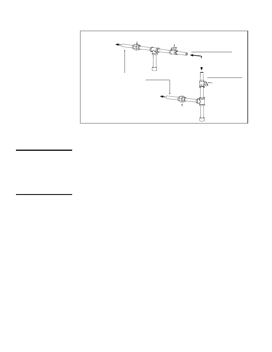
From Gas Supply
(horizontal or vertical)
Manual
shutoff
Pipe nipple extending
outside the cabinet.
Drip
Leg
To Gas Valve
(inside the
cabinet)
To Gas Valve
(inside the
cabinet)
Ground
Joint
Union
Drip
Leg
Ground
Joint Union
Manual shutoff
Horizontal Supply
Vertical Supply
6.1.2 Valve Outlet
or Orifice Pressure
Setting
Measuring valve outlet gas pressure cannot be done until the heater is in oper-
ation. It is included in the steps of the “Check-Test-Start” procedure in Para-
graph 9. The following warnings and instructions apply. Model LDAP 400 has
one gas valve; Model LDAP 800 has two gas valves; and Model LDAP 1200
has three gas valves.
WARNING: Valve
outlet gas pressure
must never exceed
3.5” w.c. for natural
gas and 10” w.c.
for propane gas.
For Natural Gas: When the heater leaves the factory, the combination gas
valve(s) is set so that the valve outlet gas pressure for a single stage valve or
high fire of a two stage valve is regulated to 3.5” w.c. Low fire on a two-stage
valve (Size 400 only) is set to 1.8” w.c. Inlet supply pressure to the heater for
natural gas must be a minimum of 5” w.c. or as noted on the rating plate and a
maximum of 14” w.c.
For Propane: When the heater leaves the factory, the combination gas valve(s)
is set so that the valve outlet gas pressure for a single stage valve or high fire
of a two stage valve is regulated to 10” w.c. Low fire on a two-stage valve (Size
400 only) is set to 5.0” w.c. Inlet supply pressure to the heater for propane gas
must be a minimum of 11” w.c. and a maximum of 14” w.c.
Before attempting to measure or adjust valve outlet gas pressure, the inlet
supply pressure must be within the specified range both when the heater is in
operation and on standby. Incorrect inlet pressure could cause excessive valve
outlet gas pressure immediately or at some future time. If natural gas supply
pressure is too high, install a regulator in the supply line before it reaches the
heater. If natural gas supply pressure is too low, contact your gas supplier.
FIGURE 6 - Gas
connection is at
the pipe nipple that
extends outside the
cabinet.
IMPORTANT: Two pipe
wrenches are required
when installing gas pip-
ing. The gas pipe that is
supplied with the heater
MUST be held with a
pipe wrench to prevent
damage to the heater.
Instructions on How
to Check Valve Outlet
(Manifold) Pressure
-- can only be done
after the heater is
installed.
Instructions
1) Locate the 1/8” output pressure tap on the first valve (See FIGURE 7).
With the manual valve turned off to prevent flow to the gas valve, connect
a manometer to the 1/8” pipe outlet pressure tap in the valve. NOTE: A
manometer (fluid-filled gauge) is recommended rather than a spring type
gauge due to the difficulty of maintaining calibration of a spring type gauge.
2) Open the manual valve and operate the heater. Measure the outlet
pressure of the gas valve. To measure low-stage pressure on a Size 400
unit equipped with a two-stage valve, disconnect the wire from the “HI”
terminal on the valve. (Be sure to reconnect wire after testing.)
Normally when operating at sea level, adjustments should not be
necessary to the factory setting(s). (For high altitude settings, see below.) If
6.0 Mechanical
(cont’d)
6.1 Gas Piping and Pressures (cont’d)
6.1.1 Gas Supply and Pressures (cont’d)