Reznor LDAP Unit Installation Manual User Manual
Page 28
Form I-LDAP, P/N 207733R6, Page 28
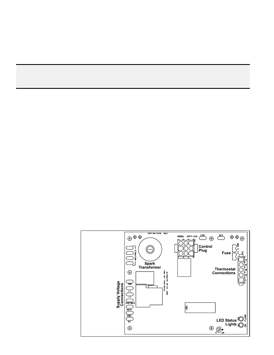
Each heat section in this
heater is equipped with
a direct spark integrated
control module (circuit
board). The module
monitors the safety
devices and controls the
operation of the fan and
venter motors and the
gas valve between heat
cycles.
8.5 Ignition System
8.4 Adjustable Air
Destratification
Fan Control
An adjustable fan control is located on top of the first heat section. It is adja-
cent to the circulating air fan and motor and controls the fan motors in all heat
sections. The purpose of the fan control is to energize the fan motor(s) when
the ambient air temperature around the heater reaches the setting on the con-
trol. The fan motor(s) will be de-energized when the fan control is satisfied.
The fan(s) re-circulates the heated air near the ceiling down to the floor level
(destratification) and improves heat recovery. A call for heat by the thermostat
overrides the air destratification fan control.
Set the adjustable fan control for the desired temperature setting for energiz-
ing the circulating air fan(s). The fan control setting should be set 5 to 10°F
higher than the wall-mounted thermostat setting. The heater is factory wired
to energize the fan(s) at medium speed when energized by the adjustable fan
control. For lower mounting heights it may be desirable to operate the fan(s) at
low speed. Switching the blue (medium speed) and red (low speed) fan motor
wires on each heat section will change the fan motor(s) speed. Refer to the
wiring diagram for the wire locations.
To manually override the fan control, the heater may be tuned off at the circuit
breaker in the main electrical panel, or a field-installed electrical box with a
SPST switch can be located near the wall thermostat with the switch wired in
series with the fan control.
The air destratification can also be a benefit in the summer time. Using the
fan(s) in the summer time can improve working conditions by alleviating stag-
nant air conditions and creating a cooling effect for the occupants.
8.3 High Limit Control
Each heat section is equipped with a temperature activated, manually reset
high limit control. The high limit control is located at the top of each heat sec-
tion. It is factory set and is non-adjustable. If the setpoint is reached, the high
limit control acts to interrupt the electric supply to the gas valve in that heat
section. If the high limit control activates, identify and correct the cause before
resetting the switch. Refer to the Maintenance Section for information on prob-
able causes . (For location, see
FIGURE 22, page 35.)
DANGER: If a manual reset high limit control activates, identify and correct the
cause before resetting the switch. Never bypass the high limit control; hazardous
conditions could result. See Hazard Intensity Levels, page 2.
FIGURE 20 –
DSI
Integrated
Control
Module
(circuit
board) in
Each Heat
Section
8.0 Controls and
Operation
(cont’d)