0 mechanical (cont’d), 1 gas piping and pressures (cont’d), 2 unit discharge – Reznor LDAP Unit Installation Manual User Manual
Page 14: Instructions for high altitude derate (cont’d)
Form I-LDAP, P/N 207733R6, Page 14
Adjust pressure by turning the regulator screw IN (clockwise) to increase
pressure or OUT (counterclockwise) to decrease pressure.
Two-Stage Low Fire - Disconnect the wire from the “HI” terminal on the
gas valve and check the low fire pressure. Turn the regulator screw to
adjust the low fire outlet pressure to the “Low Fire” pressure selected from
the table. Re-connect the wire to the gas valve.
4. Turn up the thermostat. Cycle the burners once or twice to properly seat
the adjustment spring in the valve.
Re-check the pressure(s). When the outlet pressure is right for the
installation, remove the manometer and replace the cap.
Check for leak at the pressure tap fitting.
5. If installing a Model LDAP 800, repeat the adjustment at the second single-
stage gas valve. If installing a Model LDAP 1200, repeat the adjustment at
the second and third single-stage gas valves.
6. With the heater operating determine that the inlet pressure to the heater for
natural gas is between 5 and 13.5 inches w.c. and for propane between 10
and 13.5 inches w.c. Take this reading at the inlet pressure tap of the first
gas valve. If the inlet pressure is not within the specified range, the inlet
pressure must be corrected and Steps 3 - 5 repeated.
7. Find the High Altitude Adjustment label in the plastic bag that contained
these instructions. Using a permanent marker, fill-in the appropriate
information from the “BTUH Input & Capacity by Altitude” Table, below.
Select a location for the label on the outside of the heater main access
panel so that it will be conspicuous to anyone operating or servicing the
heater. Be sure the surface is clean and dry and adhere the label.
6.0 Mechanical
(cont’d)
6.1 Gas Piping
and Pressures
(cont’d)
6.1.2 Valve Outlet
or Orifice Pressure
Setting (cont’d)
High Altitude
Capacity Changes
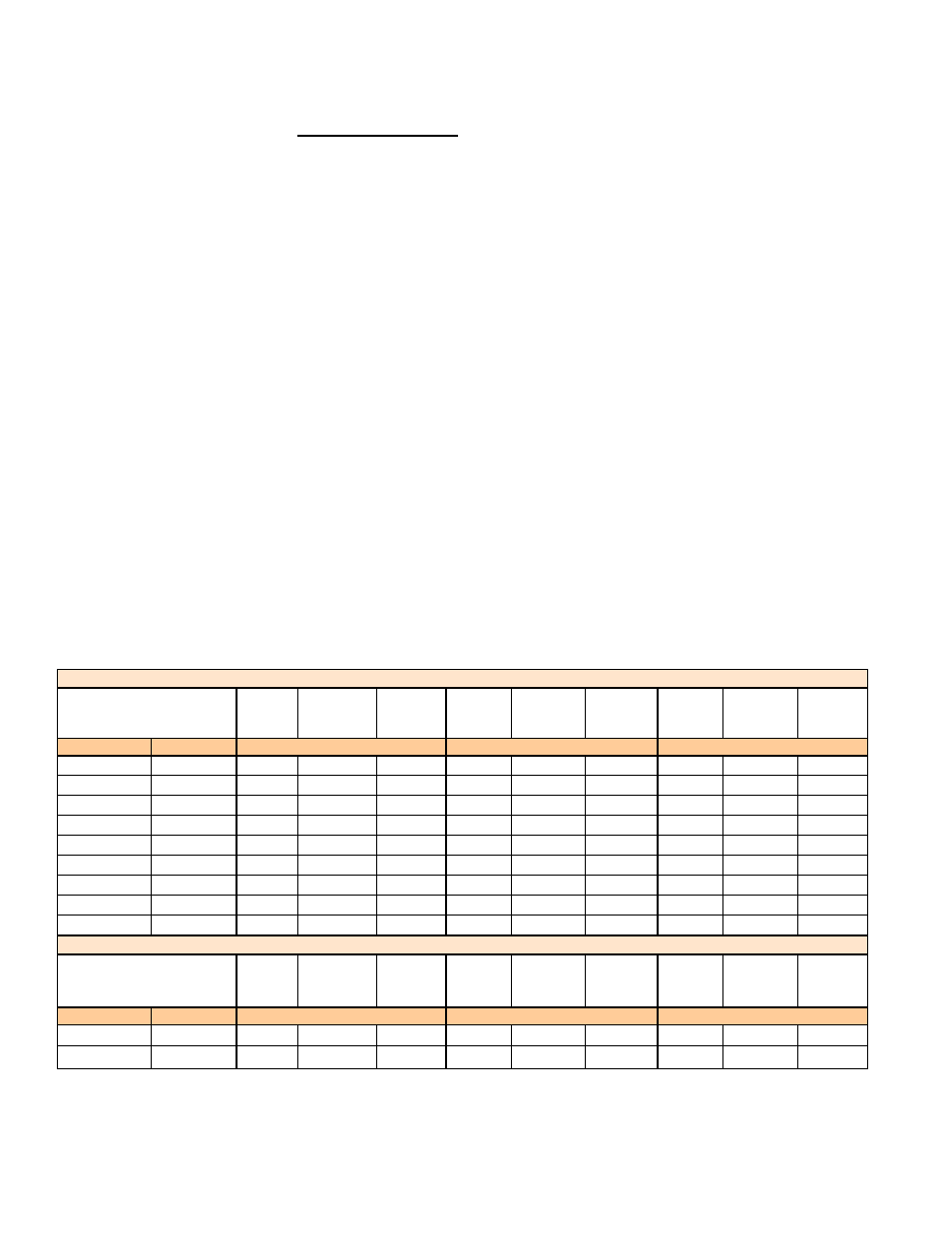
The input and/or the capacity of the heater changes with the derate. The tables
below list inputs and capacities at altitudes from sea level to 10,000 ft (3045M)
for the U.S. and to 4500 ft (1373M) for Canada.
BTUH Inputs & Capacities by Altitude in the UNITED STATES for Model LDAP
Altitude
Normal
Input
Thermal
Output
Capacity
Minimum
Input
Normal
Input
Thermal
Output
Capacity
Minimum
Input
Normal
Input
Thermal
Output
Capacity
Minimum
Input
Feet
Meters
Size 400
Size 800
Size 1200
0 - 2000
0 - 610
400000
332000
300000
800000
664000
400000
1200000
996000
400000
2001 - 3000
611 - 915
376000
312080
282000
752000
624160
376000
1128000
936240
376000
3001 - 4000
916 - 1220 368000
305440
276000
736000
610880
368000
1104000
916320
368000
4001 - 5000 1221 - 1525 360000
298800
270000
720000
597600
360000
1080000
896400
360000
5001 - 6000 1526 - 1830 352000
292160
264000
704000
584320
352000
1056000
876480
352000
6001 - 7000 1831 - 2135 344000
285520
258000
688000
571040
344000
1032000
856560
344000
7001 - 8000 2136 - 2440 336000
278880
252000
672000
557760
336000
1008000
836640
336000
8001 - 9000 2441 - 2745 328000
272240
246000
656000
544480
328000
984000
816720
328000
9001 - 10000 2746 - 3045 320000
265600
240000
640000
531200
320000
960000
796800
320000
BTUH Inputs & Capacities by Altitude in the CANADA for Model LDAP
Altitude
Normal
Input
Thermal
Output
Capacity
Minimum
Input
Normal
Input
Thermal
Output
Capacity
Minimum
Input
Normal
Input
Thermal
Output
Capacity
Minimum
Input
Feet
Meters
Size 400
Size 800
Size 1200
0 - 2000
0 - 610
400000
332000
300000
800000
664000
400000
1200000
996000
400000
2001 - 4500
611 - 1373 360000
298800
270000
720000
597600
360000
1080000
896400
360000
6.2 Unit Discharge
All Model LDAP heaters have discharge louvers but are available with addi-
tional louvers and/or nozzle discharge air options.
Optional louver and discharge nozzles are shipped separately for field instal-
lation. Model LDAP 800 and 1200 heat sections have independent airflow and
Instructions for High Altitude Derate (cont’d)