0 controls and operation, Pressure switch settings – Reznor LDAP Unit Installation Manual User Manual
Page 27
Form I-LDAP, P/N 207733R6, Page 27
8.1 Combustion Air Proving [Pressure Switch(es)]
8.2 Limit Control
Each heat section is equipped with a temperature activated auto reset limit con-
trol. The control is factory set and is non-adjustable. If the setpoint is reached,
the limit control will interrupt the electric supply to the gas valve in that heat
section. This safety device provides protection in the case of motor failure or
lack of airflow due to a restriction at the inlet or outlet. (For location, see
FIG-
URE 22, page 35.)
The combustion air proving switch is a pressure sensitive switch that monitors
air pressure to ensure that proper combustion airflow is available. The switch
is a single pole/normally open device which closes when a differential pressure
is sensed between the venter housing and the flue collection box. Each section
in the heater has a pressure switch. (For switch location, see
FIGURE 22, page
35.) In addition, heaters with more than one heat section (Size 800 and Size
1200) have a main pressure switch which senses the negative pressure in the
main venter housing.
On startup when the heater is cold, the sensing pressure is at the highest level,
and as the heater and flue system warm up, the sensing pressure becomes
less. After the system has reached equilibrium (about 20 minutes), the sensing
pressure levels off.
If a restriction or excessive flue length or turns cause the sensing pressure to
be outside the switch setpoint, the pressure switch will function to shutoff the
burner. If the main combustion air pressure switch opens, it will interrupt the
electric supply to all gas valves. If a heat section pressure switch opens, it will
interrupt the electric supply to the gas valve in that heat section. The burner(s)
will remain off until the system has cooled and/or the flue system resistance is
reduced.
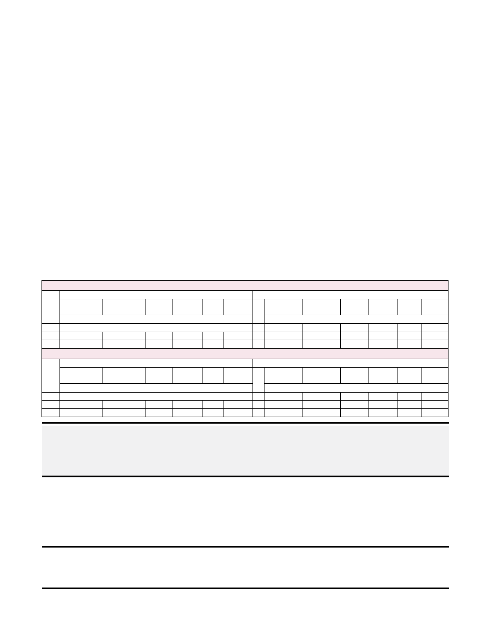
The Table below lists the approximate water column differential pressure set-
tings of the heat section pressure switch(es) and the negative pressure read-
ings of the main pressure switch.
Pressure Switch
Settings
DANGER: Safe operation of this heater requires proper venting flow. NEVER bypass
combustion air proving switch(es) or attempt to operate the heater without the venter
running and the proper flow in the vent system. Hazardous conditions could result.
See Hazard Intensity Levels, page 2.
NOTE: For high
altitude, follow
instructions in
Paragraph 8.3 to
change heat section
pressure switch(es).
The main combustion
air pressure switch
(Sizes 800 and 1200
only) does not need to
be changed for a high
altitude installation.
Sea Level Pressure Switch Settings (Applies to elevations up to 6000ft/1830M)
Model LDAP
Main Pressure Switch
Heat Section Pressure Switch(es)
Start-up Cold Equilibrium
Hot
Setpoint
OFF
Setpoint
ON
Label
Color
Switch
Part No.
Qty
Start-up Cold Equilibrium
Hot
Setpoint
OFF
Setpoint
ON
Label
Color
Switch
Part No.
Negative Pressure (in. w.c.)
Differential Pressure (in. w.c.)
400
Not Applicable
1 1.80 to 1.50 1.05 to 0.85
0.65
0.83
Yellow 197028
800 -1.30 to -1.00 -0.85 to -0.65
-0.15
-0.33
Gray 205445 2 1.90 to 1.60 1.10 to 0.90
0.65
0.83
Yellow 197028
1200 -1.40 to -0.90 -0.97 to -0.59
-0.15
-0.33
Gray 205445 3 2.40 to 1.90 1.55 to 1.00
0.65
0.83
Yellow 197028
High Altitude Pressure Switch Settings, Units Above 6000ft/1830M
Model LDAP
Main Pressure Switch
Heat Section Pressure Switch(es)
Start-up Cold Equilibrium
Hot
Setpoint
OFF
Setpoint
ON
Label
Color
Switch
Part No.
Qty
Start-up Cold Equilibrium
Hot
Setpoint
OFF
Setpoint
ON
Label
Color
Switch
Part No.
Negative Pressure (in. w.c.)
Differential Pressure (in. w.c.)
400
Not Applicable
1 1.75 to 1.45 1.00 to 0.80
0.60
0.78
Lt. Blue 197029
800 -1.25 to -0.95 -0.80 to -0.60
-0.15
-0.33
Gray 205445 2 1.85 to 1.55 1.05 to 0.85
0.60
0.78
Lt. Blue 197029
1200 -1.35 to -0.85 -0.92 to -0.54
-0.15
-0.33
Gray 205445 3 2.35 to 1.85 1.50 to 0.95
0.60
0.78
Lt. Blue 197029
8.0 Controls and
Operation
CAUTION: The auto reset limit control will shut down the heater until the cause is
corrected. Do not bypass the limit control; hazardous conditions could result. See
Hazard Intensity Levels, page 2.