Warning: pressure testing supply piping, Gas connection size, Sizing gas supply line – Reznor LDAP Unit Installation Manual User Manual
Page 11
Form I-LDAP, P/N 207733R6, Page 11
All piping must be in accordance with requirements outlined in the National
Fuel Gas Code ANSI/Z223.1a (latest edition) or CSA-B149.1 and B149.2 (See
Paragraph 1.4). Gas supply piping installation should conform with good prac-
tice and with local codes. Support gas piping with pipe hangers, metal strap-
ping, or other suitable material; do not rely on the heater to support the gas
pipe.
The heater is orificed for operation with natural gas having a heating value of
1000 (± 50) BTU per cubic ft or propane gas with a heating value of 2500 (±
100) BTU per cubic ft. If the gas at the installation does not meet these speci-
fications, consult the factory for proper orificing.
Gas Connection Size
Pipe joint compounds (pipe dope) shall be resistant to the action of liquefied
petroleum gas or any other chemical constituents of the gas being supplied.
Install a ground joint union and manual shutoff valve upstream of the heater
control system, as shown in
FIGURE 6. Installation of a trap with a minimum 3”
(76mm) drip leg is required.
To connect the gas, the heater is equipped with a nipple that extends outside
the cabinet.
Leak-test all connections by brushing on a leak-detecting solution.
Gas Connection - inches/mm
Size
Natural
Gas
Propane
400
inches
1
1
mm
25.4
25.4
800
inches
1-1/4
1-1/4
mm
31.8
31.8
1200
inches
1-1/4
1-1/4
mm
31.8
31.8
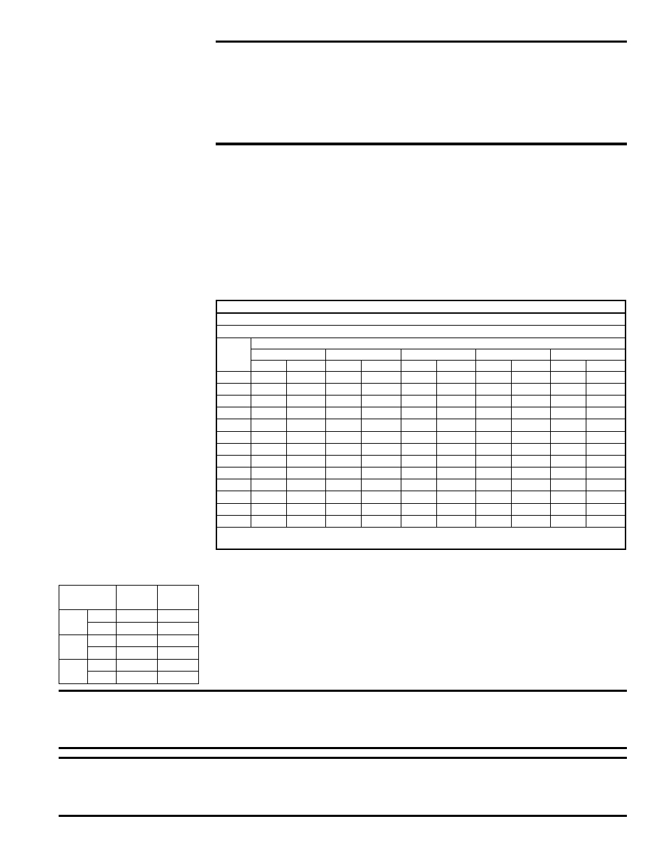
Sizing Gas Supply
Line
Capacity of Piping - Cubic Feet per Hour based on 0.3” w.c. Pressure Drop
Specific Gravity for Natural Gas -- 0.6 (Natural Gas -- 1000 BTU/Cubic Ft)
Specific Gravity for Propane Gas -- 1.6 (Propane Gas -- 2550 BTU/Cubic Ft)
Length
Diameter of Pipe
of
1”
1-1/4”
1-1/2”
2”
2-1/2”
Pipe Natural Propane Natural Propane Natural Propane Natural Propane Natural Propane
20’
350
214
730
445
1100
671
2100
1281
3300
2013
30’
285
174
590
360
890
543
1650
1007
2700
1647
40’
245
149
500
305
760
464
1450
885
2300
1403
50’
215
131
440
268
670
409
1270
775
2000
1220
60’
195
119
400
244
610
372
1105
674
1850
1129
70’
180
110
370
226
560
342
1050
641
1700
1037
80’
170
104
350
214
530
323
990
604
1600
976
90’
160
98
320
195
490
299
930
567
1500
915
100’
150
92
305
186
460
281
870
531
1400
854
125’
130
79
275
168
410
250
780
476
1250
763
150’
120
73
250
153
380
232
710
433
1130
689
175’
110
67
225
137
350
214
650
397
1050
641
200’
100
61
210
128
320
195
610
372
980
598
Note: When sizing supply lines, consider possibilities of future expansion and increased requirements.
Refer to National Fuel Gas Code for additional information on line sizing.
WARNING: PRESSURE TESTING SUPPLY PIPING
Test Pressures Above 1/2 PSI: Disconnect the heater and manual
valve from the gas supply line which is to be tested. Cap or plug the
supply line.
Test Pressures Below 1/2 PSI: Before testing, close the manual valve
on the heater.
WARNING: All components of a gas supply system must be leak tested prior to
placing equipment in service. NEVER TEST FOR LEAKS WITH AN OPEN FLAME.
Failure to comply could result in personal injury, property damage or death.
NOTE: Gas
Conversion Kits are
available for changing
from propane to natural
gas or natural gas to
propane. A factory-
authorized conversion
kit
MUST be used.
WARNING: The operating valve is the prime safety shutoff. All gas supply lines must
be free of dirt or scale before connecting the heater to ensure positive closure. See
Hazard Levels, page 2.