0 maintenance and service (cont’d), Caution: use of eye protection is recommended, 1 maintenance procedures (cont’d) – Reznor LDAP Unit Installation Manual User Manual
Page 36
Form I-LDAP, P/N 207733R6, Page 36
CAUTION: Use of
eye protection is
recommended.
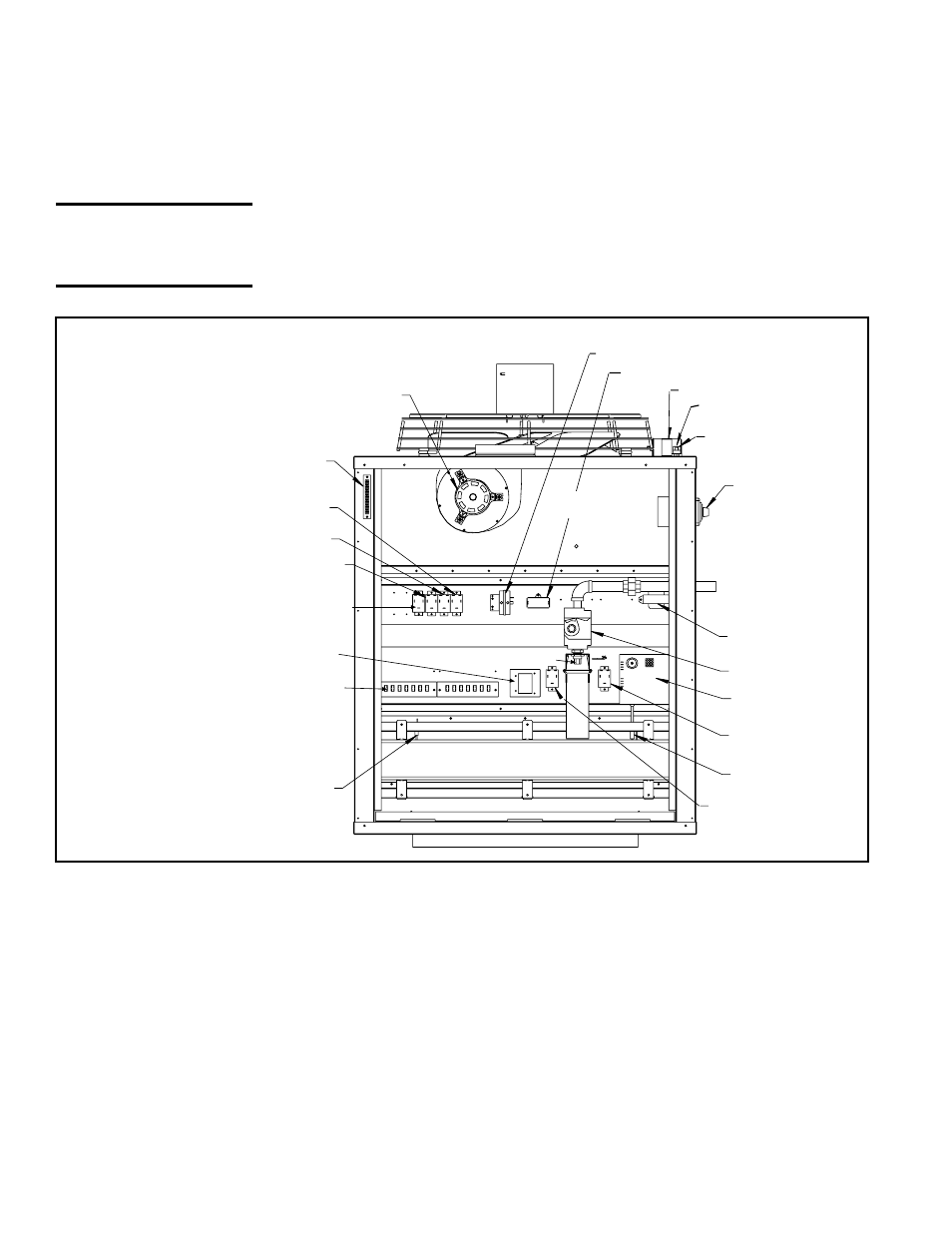
Fan
Motor
Heat Section Pressure Switch
Venter Motor Capacitor
Fan Motor Capacitor
High Limit Control
Disconnect Switch
Transformer
Gas Valve
DSI Control
(Circuit Board)
Fan Permissive
Relay
Ignitor
Heat Permissive Relay
(Models 800 and 1200)
Flame
Sensor
Terminal
Boards
Limit Control
Vent Permissive
Relay (Models 800
and 1200)
Remote Destrat
Relay
Destratification
Relay
24V Thermostat
Terminal Board
Burner Assembly
Heat Section
Venter Motor
Adjustable Destratification
Fan Control
Optional Relay
Burner Orifice
Heat Section
Flue Wrapper
With the burner assembly removed, shine a flashlight on the burner ribbons.
Look for carbon buildup, scale, dust, lint, and/or anything that might restrict flow
through the spaces between the burner ribbons. Holding the burner assembly
so that any foreign material will fall away from the burner, use a stiff bristle
brush to loosen and remove any foreign material(s). If the burner is excessively
dirty, remove one of the burner end caps. Remove the four screws that hold the
end cap to the burner housing. Lightly tap the end cap to remove it.
Clean all foreign material from the burner and venturi. After the burner is thor-
oughly clean, replace the end cap making certain that it is tight against the
burner housing.
Inspect and Clean the
Burner
Inspect the Lower
Portion of the Heat
Exchanger (with
burner assembly
removed)
At the burner flame entrance of each tube, shine a bright light into each heat
exchanger section. With the light shining into the heat exchanger, observe the
outside for visible light. Repeat this procedure with each heat exchanger sec-
tion. If any light is observed, replace the heat exchanger.
of the gas line inside of the heater. Carefully remove the burner orifice and
orifice adapter locking nut. Slide the orifice adapter out through the bracket
on the burner.
6. Remove Burner Assembly
a) Locate the three upper burner body supports. At each support, remove
the one screw that attaches it to the burner shield.
b) Holding the venturi tube, slide the entire burner assembly slightly
upward to disengage the burner from the supports on the bottom. Then
rotate the open end of the venturi tube outward toward the access door
opening. Carefully pull the burner assembly out of the cabinet.
FIGURE 23 - Burner Removal
• Size 400 has 1 burner.
• Size 800 has 2 burners.
• Size 1200 has 3 burners.
NOTE: If any of the
burner components are
damaged or deterio-
rated, replace the burner
assembly.
10.1 Maintenance
Procedures
(cont’d)
10.0 Maintenance
and Service
(cont’d)
10.1.3 Burner Maintenance (cont’d)