Appendix “a” 12vdc relay, Appendix “b” wiring specifications – Interlogix Monitor XL Hardware Guide User Manual
Page 60
56
Monitor ISM/xL™ Hardware Guide
22-0375 rev1.1
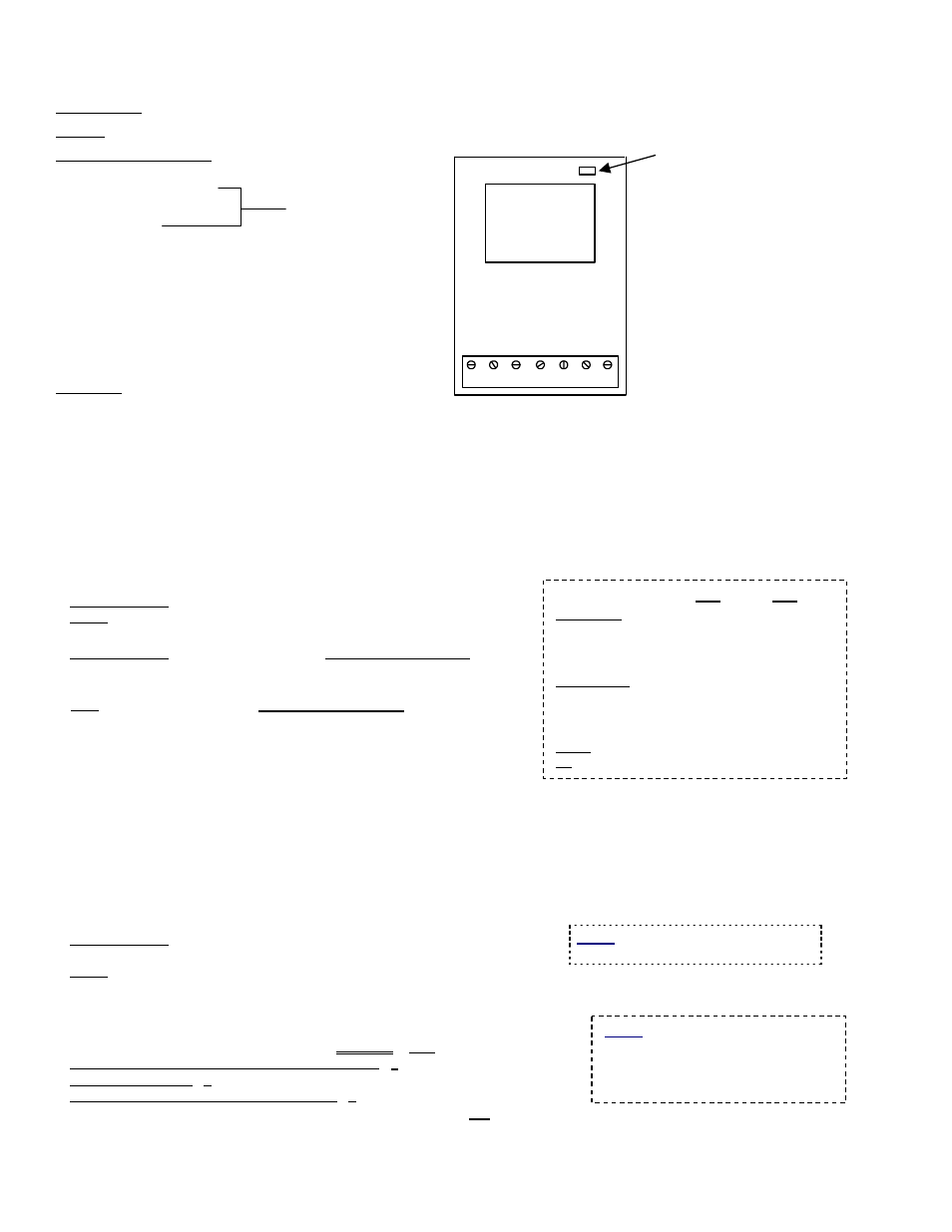
Appendix “A” 12VDC Relay
Dimensions: 1&3/8” (3.5cm) wide X 2&3/8” (6.0cm) long X 1&1/16“ (2.7cm) high.
Power: 12VDC, 8.5 mA active current rating.
Terminal Connections:
1. Normally
Closed
2. Normally
Open
3. Common
4. Positive
Trigger
5. Negative
12VDC
6. Positive
12VDC
7. Negative
Trigger
Features:
•
Form “C” contact.
•
Contact will change state when 12VDC applied to Pos. pin 6 and Neg. pin 5 and there is a wire short between
Pos. pin 6 and Pos. Trigger pin 4.
•
When continuously powered by 12VDC, will change state when:
−
Low voltage trigger applied to Pos. Trigger pin 4 (greater then 3VDC, approximately 130 micro amps).
−
A negative supply is applied to Neg. Trigger pin 7.
−
On board red LED turns on when relay activated.
Appendix “B” Wiring Specifications
•
Earth Grounds:
Recommended: 18 AWG, stranded & insulated;
Good: Standard 22 AWG quad cable (use all 4 wires).
•
Module Bus (RS485) Cabling (device comms & power):
Recommended: 24 AWG, 4 conductors, Shielded Twisted Pair,
120
Ω
impedance, low capacitance, 41 pF / meter or
12.5 pF / foot (such as Belden 9842).
ULC: 22 AWG, 4 conductors, Shielded Twisted Pair, low capacitance.
For regions that require CE conformity, C-Tick conformity or the
equivalent the recommended Module Bus cabling bus wire type
must be used.
•
Max. Length: Up to 610 m / 2000 ft. of cable on a Module bus port.
•
NOTE: For longer cable distances, and/or where many expansion
modules are connected on one cable (daisy chained, star wiring
configurations are not acceptable) a 150
Ω
‘terminating’ resistor
will need to be installed across A and B communication terminals
of the last module on the ‘bus’ cable. If necessary, add a second resistor at the panel end module bus A and B if it is confirmed
that the panel connector is the “end of line” at that end.
•
Separate Power (or door strike) Wiring:
Recommended: 18 AWG, stranded & insulated
(2 conductors; colour-coded is preferable);
Good: 22 AWG, 2 conductors, insulated.
•
Inputs/Sensor Cabling:
22 AWG, 2-wires (For electrically noisy environments, use twisted pair, and/or shielded cable.)
•
Outputs/Signalling: 22 AWG, 2 conductors.
•
Reader Cabling: 24 AWG (
ULC: 22 AWG
), shielded (Max: 150 m / 500 ft.)
Basic reader (no LEDs, buzzer control, or tamper): 4 Conductors;
Reader with LED(s): 6 conductors;
Reader with LEDs, plus buzzer and tamper: 9 conductors.
Modem/PC Link:
Use kit provided, or 22/24 AWG low-cap cable (not reader cable). Shielded cable is recommended.
RS485 (shared cable or modem): 3 wires, see Module bus spec. above.
Red LED turns
on when relay
activated.
1 2 3 4 5 6 7
12V Relay
P/N 650-0912
NC
NO
CO
M
+ve
T
rig
-v
e
12V
D
C
+v
e
12
VD
C
-ve
Tr
ig
In
non-energized
state.
Cabling P/Ns:
FT4
FT6
Module Bus (shielded)
Preferred (24 AWG):
120-3401
120-3405
ULC (22 AWG):
120-3408
120-3409
Note: Max. distance may be reduced with the ULC cable.
Reader cable (24 AWG shielded):
6 Conductors:
120-3402
120-3406
10 Conductors:
120-3403
120-3407
Note: ULC requires 22 AWG shielded cable.
Power (18 AWG):
120-3400
120-3404
I/O (quad):
120-3410
120-3411
Notice: Elevator controller and
condominium keypad installations
include unique power and cabling
aspects. Always refer to the installation
instructions provided with each device.
Notice: Use minimum 26AWG UL/CSA/or
equivalent approved telephone cable.