Keypad, Enter code – Interlogix Monitor XL Hardware Guide User Manual
Page 55
22-0375 rev1.1
Monitor ISM/xL™ Hardware Guide
51
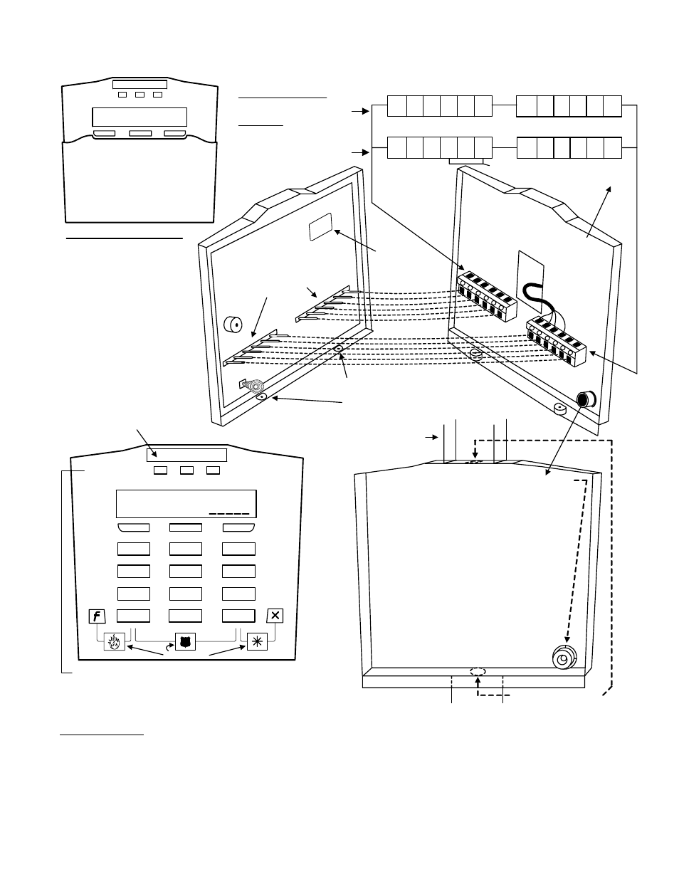
Keypad
1
,
- #
2
ABC
3
DEF
4
5
JKL
6
MNO
GHI
7
8
TUV
9
WXY
PRS
Keypad LEDs
Red Flashing:
Protection ON
Solid: Partial
protection (STAY)
Green On Always
with power present.
Yellow On when
trouble condition
present. Flashing when
there is no AC mains.
Red Green Yellow
ComsLost #50624
ef
Enter
code
4
2 8 2
2
0
Z_Q
X
X
To use the keypad tamper spring as a wall tamper
break out this plastic cylinder inside the back cover.
Screw it to the wall, keeping it in the same hole as it
was attached, so the back cover fits over it.
The plastic cylinder prevents the spring from being
affected by flat objects wedged in behind the
keypad.
The additional keypad base is optional. For
installations using it there is a similar, shorter,
washer style, plastic break out.
Place it behind the plastic cylinder and screw
them down together.
Then place the holes in the base and keypad
backing over top of them.
Fit the spring inside the plastic cylinder part
and secure the keypad front to the keypad
back. The spring compressing should reset
the keypad tamper condition.
Knock outs for rectangular
conduit using additional
keypad base.
Key
pad
Bac
k
Ke
ypa
d F
ron
t
Circuit board pin connectors insert
into fixed terminal blocks on inside
of keypad back. This allows the
keypad to make wire connections
in the terminal blocks.
Terminal
Block
Te
rm
ina
l B
loc
k
Tamper Spring
Sonalert
Cable
After placing the keypad on its back
section, make sure the keypad's securing
screws (supplied) are always I N !
Standard and G-ProxII
1
4
3
2
5
6
PT1 0V PT2 PT3
PT4
1
4
3
2
5
6
A
B
0V
OUT
+12V
0V
Wiegand
1
4
3
2
5
6
D1
D0
1
4
3
2
5
6
A
B
0V
OUT
+12V
0V
0V
PT1
PT2
Keypad Terminal Block Wiring
Module Bus
Module Bus
Ou
tp
ut
Inpu
t 1
In
pu
t 2
Co
m
m
o
n
Wiegand Reader Data 1 and 0.
No reader LED connection.
Wall tamper
knock out
Flip Cover
Serial # sticker
for programming
into Module
Programming.
Apply dealer's logo label (supplied) in
the indented space at the top of the
keypad. Apply the Alert Button labels
as required.
Alert Labels
XX
XX
X
Rectangular Conduit
(Trunking)
Keypad Output
goes negative.
Interface with a
relay or power
supply. Common
their negatives
with keypad 0V.
Module Point Assignment: 8
points.
First point: Fire Alert buttons
Second point: Panic (Hold-
Up) buttons
Third point: Auxiliary Alert
buttons
Points 4 – 7 are hard wire
inputs 1 – 4 on the Standard
and G-ProxII version.
Points 4 – 5 are hard wire
inputs 1 – 2 on the Wiegand
version. All unused points
are skipped.
Point
4 – 7
Point
4 – 5
Point 1
Point 2
Point 3
Ratings:
LCD Keypad with Reader
Input: 12VDC, 110mA
Output: 12VDC, 1x10mA
LCD Keypad
Input: 12VDC, 95mA
Output: 12VDC, 1x10mA
Temp for both: -10°C to
+55°C (14°F to 131°F) @
93%
Future
Future
3 Keypad Versions
•
LCD Keypad P/N 111-3610 (white), 111-3620 (gray): standard keypad includes 3 programmable alert button inputs, 4 hardwire
alarm input points and 1 output point.
•
LCD Keypad with RF reader P/N 111-3611 (white), 111-3621 (gray): keypad includes 3 programmable alert button inputs, 4
hardwire alarm input points and 1 output point. Includes a built-in RF G-Prox reader.
•
LCD Wiegand Keypad P/N 111-3612 (white), 111-3622 (gray): keypad includes the capability to connect an external Wiegand
reader to it. Keypad includes 3 programmable alert button inputs, 2 hardwire alarm input points and 1 output point.
Refer to Installation Instructions P/N 21-3610 for further information.