Fire module – Interlogix Monitor XL Hardware Guide User Manual
Page 28
24
Monitor ISM/xL™ Hardware Guide
22-0375 rev1.1
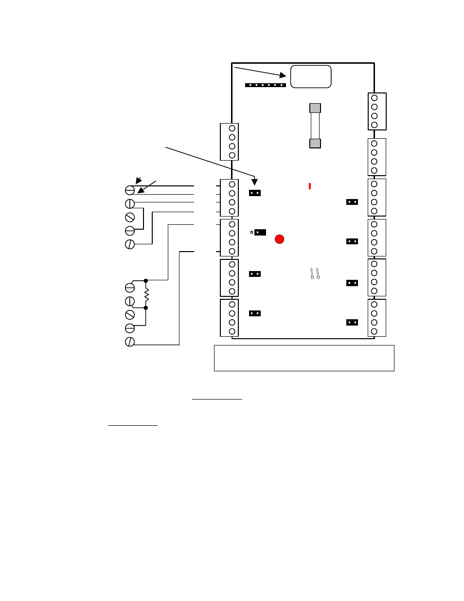
Fire Module
14
3
2
(+) 12V
Data A
Data B
14
3
2
F1
1/
2
A
M
P
P/
N 34
2-
33
56
14
3
2
0V
O/P1
O/P2
Switched (+)
Switched (
-
)
(
-
)
(
-
)
(+) 12V
(+) 12V
(+) 12V
0V
M
o
dul
e
B
u
s
Au
x P
o
we
r
red
green
yellow
black
Tamper Pins
LED 2
follows O/P1
Annunciator
output board
male plug.
TB14
TB9
TB13
Fire Module
LED 1 Bus
communications
indicator
14
3
2
14
3
2
14
3
2
14
3
2
14
3
2
14
3
2
14
3
2
14
3
2
loop 1
loop 1
loop 2
loop 2
loop 1
loop 1
loop 2
loop 2
loop 1
loop 1
loop 2
loop 2
loop 1
loop 1
loop 2
loop 2
loop 1
loop 1
loop 2
loop 2
loop 1
loop 1
loop 2
loop 2
loop 1
loop 1
loop 2
loop 2
loop 1
loop 1
loop 2
loop 2
INP
U
T
2
IN
PU
T5
IN
PUT6
IN
PU
T7
IN
PU
T
8
IN
PU
T
1
INP
U
T
3
INP
U
T
4
Jumper for each input.
IN = Input wired Class "A"
(double loop)
OUT = Input wired Class "B"
(normally open, 2.2K resistor
end of line).
Jumper OUT
Class "A" Wiring
(fire switches)
normally closed
normally open
common
closed tamper
closed tamper
A
la
rm
C
on
ta
ct
Tamper
(if existing)
normally closed
normally open
common
closed tamper
closed tamper
2.
2
K
A
la
rm
C
on
ta
ct
Tamper
(if existing)
Class "B" Wiring
(door contacts, PIRs)
Jumper IN
NOTE: Do not twist pairs
together under connections.
Keep connections separate.
red
green
yellow
black
black
yellow
Current Rating = 25mA without annunciator card.
60mA with annunciator card and all LEDs on.
5 digit serial number to
program in Module
Programming
XXXXX
•
Capacity of 8 inputs and 10 outputs (with standard plug on output annunciator card).
•
With jumper settings illustrated, inputs can be wired class “A”. A short between the 2 loops wired between normally
open connections = alarm. Either loop opening = tamper. Most commonly used to monitor water flow sprinkler
alarm switches.
Or the inputs can be wired class “B”. A short across the 2.2K end of line resistor between normally open
connections = alarm. Resistor loss = tamper. This connection can be used to monitor sprinkler switches such as
water pressure and gate valve but can also be used as burglary inputs.
•
Whether the point is class “A” or “B”, fire or burglary, the point circuit type is always “0” normally closed. Any point
type may be used. However, for a class “A” fire point, it must be defined as “010” = Fire Class A.
•
For an approved fire monitoring system, an 18V, 40VA, AC transformer (P/N 859-0052) must be installed on the
control unit box. This txmr. has two 18V secondary white leads connected to motherboard AC input. The txmr.
primary is then fastened to an AC supply (e.g. 2X4 electrical box, P/N 573-3735 and cover, P/N 573-3742).
•
For ULC applications all cabling connected to the fire module MUST be run inside armored BX flex cable. From fire
module to sprinkler switches and Module Bus line from fire module directly back to main control unit.
•
When programming outputs, this board is similar to the 8/16 input/output expander module. Outputs 3 to 8 do not
exist. Therefore, if the outputs on the annunciator card are required, the module is programmed with 16 outputs.
The 1
st
and 2
nd
output can be programmed. Outputs 3 to 8 are skipped. Outputs 9 to 16 can be programmed on the
annunciator card.
Refer to Installation Instructions P/N 22-0367 for further information.