Vigil module, Module programming – Interlogix Monitor XL Hardware Guide User Manual
Page 32
28
Monitor ISM/xL™ Hardware Guide
22-0375 rev1.1
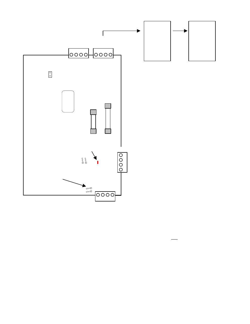
Vigil Module for use in the UK
Standard
Tamper
Pins
LED Bus
communications
indicator
TB1
Vigil Module
14
3
2
XXXXX
1
4
3
2
1
4
3
2
Module Bus
Da
ta
A
Da
ta
B
(+
) 1
2
V
0V
red
gr
e
e
n
y
e
llo
w
bl
ack
Tamper Pins
F1
1/
2
A
M
P
P
/N
34
2-
3
356
Module Bus
Data A
Data B
(+) 12V
0V
red
green
yellow
black
F2
1 AM
P
P/
N
342
-3
3
5
0
1
4
3
2
re
d
gree
n
ye
llow
bl
ac
k
re
d
gree
n
ye
llow
bl
ac
k
Cl
oc
k
Da
ta
(+) 1
2
V
0V
Cl
oc
k
Da
ta
(+) 1
2
V
0V
Vigil Concentrator
Bus
Vigil
Concentrator
Bus
TB1A
TB2
A
TB2
2 identical MONITOR Module
Bus connections. Can be
interconnected between main
panel and other modules on one
connector. Leave one connector
open to connect LCD service
keypad for convenience.
2 identical Vigil Concentrator
Trunk Line connectors.
Vigil
Concentrator
# 1
Vigil
Concentrator
# 2
These jumper
pins not used
and left open
These tamper pins engage
when drill through housing
version used to monitor short
between housings.
5 digit serial
number to
program in
MONITOR
Module
Programming
NOTE: A Vigil Concentrators can be
any of a number of varied types of
modules used in a Vigil System.
Similar to the Modules used with a
MONITOR System.
Module Programming
•
The Smart/Vigil Module is capable of 64 input points and 80 output points to match the number available with a
full size Chubb Smart system.
•
For easier programming of inputs/outputs the Smart/Vigil module must occupy the first module position in the
ISM/AFx Module Group.
•
Enter the module’s 5-digit address in Module programming.
•
It may be left assigned to Area 1 and enable the module’s tamper.
•
Inputs and outputs are programmed differently from other modules to achieve the full amount on a Chubb
Smart/Vigil system.
•
The Smart/Vigil module is 3 modules in one. It has 3 module group addresses.
•
If a Smart/Vigil module was taking over a full 64 inputs and 80 outputs, this first address would be programmed
with “7” = 32 inputs and “7” = 32 outputs.
•
Press
Save
. In the following module address, enter the next consecutive number after the last address. E.g. if the
Smart/Vigil module’s original address number was “15281” in this second module address enter “15282”.
•
Program the same as the last address with “7” = 32 inputs and “7” = 32 outputs.