Graphic map module cont – Interlogix Monitor XL Hardware Guide User Manual
Page 30
26
Monitor ISM/xL™ Hardware Guide
22-0375 rev1.1
Graphic Map Module cont.
A1
A2
A10
A9
A8
A7
A6
A5
A4
A3
F1
F2
F10
F9
F8
F7
F6
F5
F4
F3
E1
E2
E10
E9
E8
E7
E6
E5
E4
E3
D1
D2
D10
D9
D8
D7
D6
D5
D4
D3
C1
C2
C10
C9
C8
C7
C6
C5
C4
C3
B1
B2
B10
B9
B8
B7
B6
B5
B4
B3
G1
G2
G10
G9
G8
G7
G6
G5
G4
G3
Green
LED
Green
LED
Green
LED
Green
LED
Yellow
LED
Yellow
LED
Yellow
LED
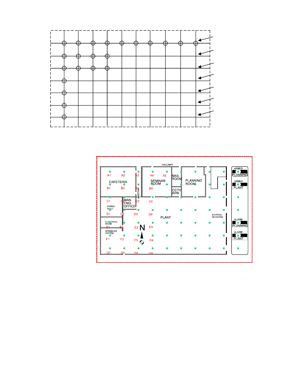
LED position IDs on face correspond with those on PIN strip. All LEDs are RED except as shown.
MANUFACTURING FLOOR AREA
Using the Graphic Map
Module drawing software
can produce a diagram
similar to this. Points of
interest can be labeled
and illuminated for any
programmable output
condition by strategically
assigning the outputs to
the LEDs.
LED ID letters and numbers are
displayed in this example only.
A printed out drawing will not
show them.