Mu lt i- do or controller, Multi-door controller, Tb 2 – Interlogix Monitor XL Hardware Guide User Manual
Page 38: Tb 1, Powe r li nks fo r do or s trik e s, Ps for d oor st rikes, Door loc k deta il ba ckup batt eries, Batter y p/s p/s, Gro undi ng, Upgra d ing the d oor capac ity
34
Monitor ISM/xL™ Hardware Guide
22-0375 rev1.1
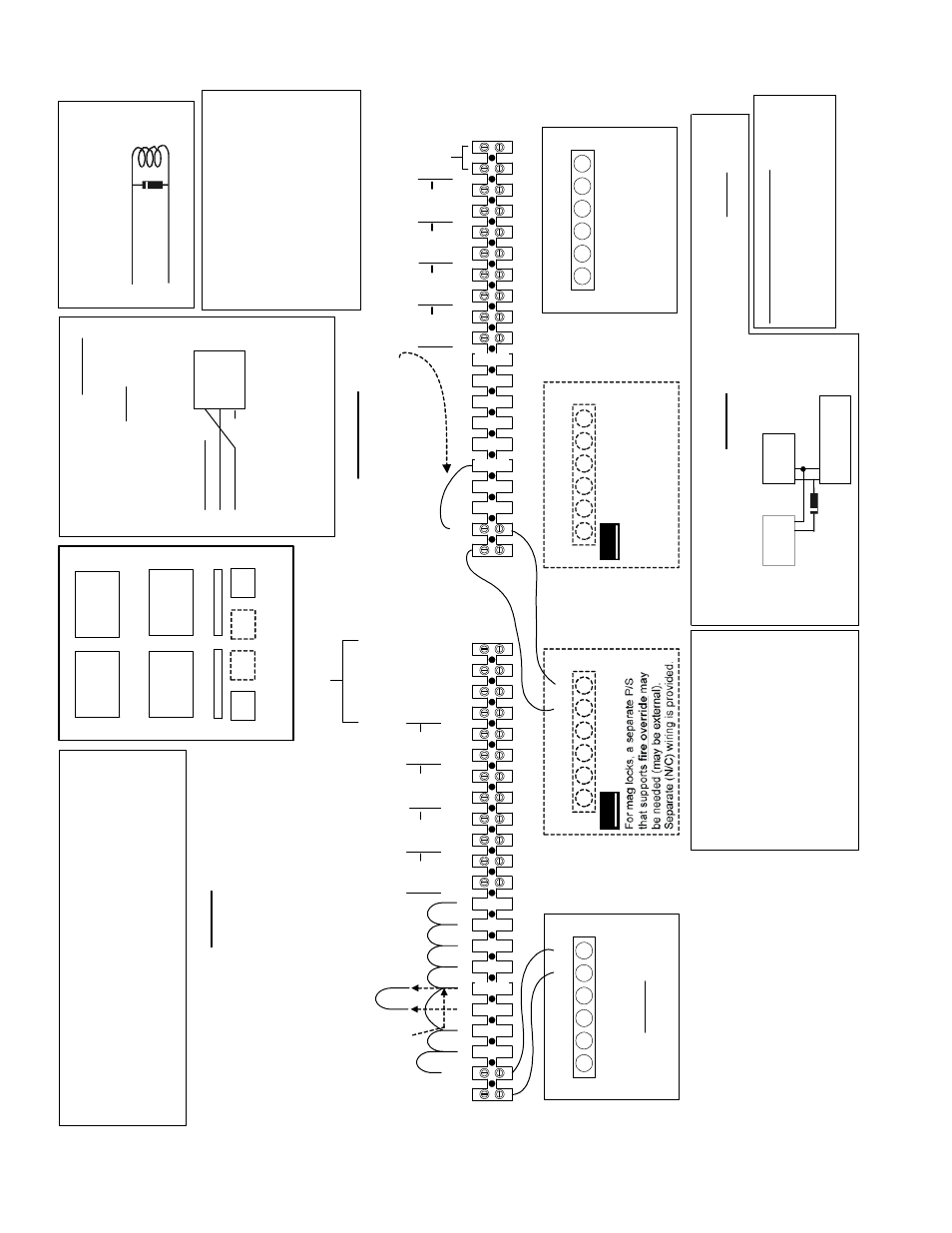
Multi-Door Controller
12
3
4
56
78
9
10
11
12
13
14
15
16
17
18
19
20
(
-
)(
+
)
(
-
)(
+
)(
-
)(
+
)
(
-
)(
+
)
(
-
)(
+
)
T
B
2
No
t
Us
ed
AC
AC
(+)
(
-
)(
+
)
(
-
)
DC
BA
T
Pow
er L
in
k
s
f
o
r M
a
g
Locks
Door
5
Lock
Do
or
6
Loc
k
Door
7
Lock
Door
8
Lo
c
k
12
3
4
56
7
8
9
1
0
1
1
12
13
14
15
1
6
17
1
8
19
20
21
22
(
-
)(
+
)(
-
)(
+
)
(
-
)(
+
)(
-
)(
+
)
(
-
)(
+
)
Powe
r
Li
nks fo
r Do
or S
trik
e
s
(M
om
en
ta
ry
P
o
wer
)
(+) pass-through
A
B
T
B
1
AC
A
C
(+)
(
-
)(
+
)
(
-
)
DC
BA
T
PS
for D
oor
St
rikes
M
o
d
u
le
Bu
s
Co
nne
ct
ions
Door
1
Lo
c
k
D
oor
2
Lo
c
k
Door
3
Lo
c
k
Door
4
Lo
c
k
©
2
0
0
3
C
S
G
Se
cu
ri
ty
In
c.
/
Sé
cur
it
é
CSG
I
n
c.
4
5
2
-9
1
5
1
v1
.2
(
O
ct
2
0
0
3
)
(
-
)
(+
)
120-
8520
(A) In and Out
(B) In and Out
(-) In and Out
120-8
5
2
0
Door1
Door2
Door3
Door4
Door5
Door6
Door7
Door8
T
h
e M
u
lt
i-
Do
or
C
ont
rol
le
r i
s
pre
-w
ire
d
to
p
o
wer
8
D
o
ors w
it
h
D
o
o
r
S
tr
ike
s.
If
a
d
oor
req
u
ir
e
s
m
ag
lo
c
k
po
we
r
in
st
ea
d,
r
e
m
o
v
e
t
h
e
lin
k
f
o
r t
h
e
door
n
u
m
b
e
r s
tri
k
e
and
j
u
m
p
t
h
e pr
evi
o
u
s
do
or’
s
st
ri
k
e
pow
er
t
o
th
e ne
xt
do
o
rs’
.
E
x
am
p
le:
D
oor
3
h
a
s a
m
a
g
l
o
c
k
.
R
e
m
o
v
e
t
he pr
e-w
ired
j
u
m
per
be
tw
ee
n
d
o
o
r 3 and
4
an
d m
o
v
e
t
h
e co
nne
ct
ion f
rom
3
t
o
4 t
o
co
nt
in
ue
su
pp
ly
in
g
po
w
e
r
to
t
h
e
r
e
m
a
in
in
g
do
o
rs
.
By
p
a
s
s
Re
m
o
ve
Do
or
C
o
n
tr
o
lle
r 1
Do
or
C
o
n
tro
lle
r 2
Door1
Door2
Door3
Door4
Door5
Door6
Door7
Door8
Doo
r
Con
trol
le
r 3
Do
or
C
o
n
tro
lle
r 4
C
o
n
ti
n
ue
d a
t Po
wer Link
s
for Mag L
o
cks TB2
E
xam
pl
e:
Do
o
r
3 ha
s a m
a
g
l
o
c
k
. A
ft
e
r
it
s st
ri
k
e
po
we
r
ju
m
per
ha
s
be
e
n
by
pa
ss
e
d
,
ad
d
a j
u
m
p
e
r
fo
r i
ts pos
it
iv
e m
ag p
o
w
e
r.
S
u
ppl
y
m
ag
p
o
w
er
t
o
ea
ch
d
oor
us
in
g
a m
a
g,
i
n
t
h
e
s
a
m
e
wa
y
.
Door
Loc
k
Co
il
+
+
-
In
st
al
l diode or
M
O
V
cl
os
e t
o t
he lock [
D
C
st
rike,
or
m
ag.
lock w/
o rev
. c
oils:
Use
D
iode.
Ot
herw
ise,
inst
al
l 27
V
M
.O.
V
.]
-
Door Loc
k
Deta
il
Ba
ckup
Batt
eries
E
a
c
h
po
w
e
r su
pp
ly
r
equ
ir
e
s
a
se
p
a
ra
te
b
a
tt
e
ry
.
T
hes
e m
a
y n
eed t
o
be s
m
al
le
r
than
7 A
h
to
fit
in
to
t
h
e
ca
b
in
e
t.
Exc
e
pt
ion:
If
yo
u
m
u
st
sha
re
a
ba
tt
e
ry be
tw
een
2 P
/S
s
,
in
sert
a
di
ode
i
n
t
h
e
B
A
T
(+)
c
onne
c
ti
o
n t
o
t
he
s
e
c
ond
P
S
.
Batter
y
P/S
P/S
+
+
+
-
-
-
E
n
s
u
re
ea
ch
ca
bi
ne
t i
s
c
onn
ec
te
d
to
a l
o
ca
lly
-ap
pro
v
e
d
ear
th
g
rou
nd
usi
n
g
at
l
e
ast
18 A
W
G wi
re.
Do no
t co
nne
ct
a
n
y
th
ing e
ls
e
t
o
t
h
e
eart
h
gr
ou
nd.
Conn
ec
t t
he M
o
dul
e B
u
s c
abl
e
shi
e
ld
s
toge
th
er
i
n
s
ide
ea
ch
c
a
b
in
e
t
and o
n
ly
c
onne
ct
t
h
e
s
h
ie
ld
t
o
ea
rt
h
groun
d
at
t
h
e
IS
M
pan
el
.
Gro
undi
ng
J
u
m
per
S
tri
k
e
and
m
a
g
l
o
c
k
con
nec
ti
o
n
s
a
re
p
re-
wi
red b
e
twe
en
t
he
d
oor
c
ont
ro
lle
r bo
ar
ds and
t
h
e
tw
o l
a
rge
t
e
rm
in
a
l s
tr
ip
s
ne
ar
t
he b
o
tt
om
o
f t
he cab
ine
t.
M
o
d
u
le B
u
s
co
nnec
ti
ons
are
pr
ov
id
e
d
as
wel
l.
Ot
he
r con
n
e
c
ti
ons
(
s
uch
as re
ad
er ca
bl
e
s
, d
oor
c
ont
ac
ts
, et
c
.)
c
onn
ec
t d
ir
e
c
tl
y
t
o
t
he do
or co
nt
ro
ller boa
rds
.
F
o
r do
or
-s
tr
ik
e
a
nd m
a
g l
o
ck i
n
st
ru
c
ti
o
n
s
,
re
fe
r
to
t
h
e
"P
ow
e
r
Li
nks
" se
ct
io
n
s
.
Mu
lti -
D
o
o
r Con
tro
ller Ge
ne
ra
l W
iring
Do
or
C
o
n
tr
o
lle
r 1
Door
Con
trol
le
r 2
Do
or
C
o
n
tr
o
lle
r 3
D
oor
C
ont
ro
lle
r 4
D
oor
1
D
oor
2
Do
or
3
Do
or
4
Door
5
D
oor
6
Do
or
7
Do
or
8
M
u
lt
i-
Do
or
Co
n
tr
o
ll
e
r C
a
bi
n
e
t
TB1
TB2
Th
e 4
-6
d
oor
an
d
4-
8
doo
r
upgr
ad
e
k
it
s
i
n
cl
u
de do
or
-con
tr
ol
le
r
b
oar
d(
s),
a p
o
w
e
r su
ppl
y
, an
d m
o
u
n
ti
n
g
ha
rdw
a
re
.
Th
e w
iri
ng
har
nes
s
is
p
re
-wi
red t
o
po
we
r t
h
e add
it
io
n
a
l do
or co
nt
ro
lle
r
bo
ard
(s
) f
rom
t
h
e se
con
d
P
/S
.
U
pgra
d
ing
the
D
oor Capac
ity
AC
A
C
(+)
(
-
)(
+
)
(
-
)
DC
BA
T
`
Ad
d
PS fo
r Ma
g lo
cks
AC
AC
(+
)
(
-
)(
+
)
(
-
)
DC
BA
T
Requir
e
d
f
o
r 8
-d
oor
unit
s
.
In
c
lu
d
ed in 4-
8
d
oor
upgr
ade
k
it
s
.)
`
Add
PS
for
D
oor
Con
trol
lers
3
&
4
1
2
0
-8520
(
M
ai
nt
ai
ned
P
o
w
e
r)
PS
f
o
r
D
o
o
r
Co
ntrol
lers 1
& 2
T
h
e
de
fa
ult
do
or s
trik
e
w
iring is
f
o
r
"F
a
il-Se
c
u
re"
(
pow
ere
d
=
un
loc
k
e
d
).
F
o
r "F
ai
l-Saf
e
"
door
s
trik
e
s
(pow
ered
= loc
k
ed),
c
o
nnec
t
to
t
h
e
la
rge
te
rm
inal
s
tr
ips
a
s
us
ual,
AN
D
at
e
a
c
h
a
pplic
ab
le D
o
or C
o
nt
roller
Unlo
c
k
Re
la
y
,
mo
ve
th
e
N/O
w
ir
e
to
N/
C
te
rm
in
a
l:
Fa
il-S
a
fe D
oor S
trikes
N/
C
Co
m
N/
O
1 2 3
X
X
Mu
lt
i-
Do
or
Controller
T
he s
y
s
te
m
s
h
all not
b
e
i
n
s
tall
ed in t
h
e
fa
il s
e
c
u
re
m
ode
unle
s
s
pe
rm
it
te
d b
y
t
h
e
lo
c
a
l aut
h
o
ri
ty
h
a
v
ing jur
is
d
ic
ti
on
an
d
s
h
a
ll not
in
te
rf
er
e wit
h
t
h
e
ope
ra
ti
on o
f
p
anic
har
dwar
e
.
2
D
o
or
C
ont
roller R
a
ti
ngs
In
put
: 1
2
V
D
C
, 8
40m
A
Out
p
ut
: 1
2
V
DC
, 4
0
m
A
(A
ux
ili
a
ry
po
we
r)
12
V
D
C,
50
0m
A
or
5V
DC
, 240
m
A
(R
ead
er
p
o
we
r)
F
o
r us
e i
n
2 Do
or C
ont
rol
le
r
m
odel
s:
9
5
0
-901
1,
950
-90
12,
95
0-9
013
, 950
-90
1
4
S
ee Tw
o Doo
r
C
o
nt
rol
le
r I
n
s
tal
la
ti
on
In
s
tru
ct
ions
: 2
2
-0
35
3
For U
L
I
n
st
allat
ions
16V
, 40V
A
16
V
, 40
V
A
16
V
, 40
V
A
16V
, 40V
A
120-8520