Version 2 door module, Do o r 1 do o r 2 – Interlogix Monitor XL Hardware Guide User Manual
Page 37
22-0375 rev1.1
Monitor ISM/xL™ Hardware Guide
33
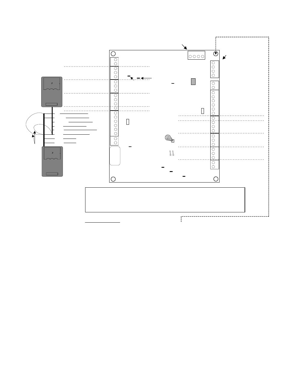
Version 2 Door Module
14
3
2
56
13
2
14
3
2
14
3
2
Module Bus
(+
)1
2
V
(
-
)0
V
D
a
ta
B
D
a
ta
A
(+)12V
(
-
)0V
Data A
Data B
Normally Open
Common
Auxiliary Relay
DO
O
R
1
DO
O
R
2
Normally Closed
Common
Normally Open
Auxiliary Input
Door Unlock Relay
Common
Request to Exit
Door Contact Input
Common
Reader Tamper
Reader Buzzer Negative
5V
12V
Reader
Voltage
Jumper
(+)5/12VDC
Green LED
Red LED
Data 1 Clock
Data 0
Ground 0V
Normally Open
Common
Normally Closed
Common
Normally Open
Common
Request to Exit
Door Contact Input
Common
Reader Tamper
Reader Buzzer Negative
(+)5/12VDC
Green LED
Red LED
Data 1 Clock
Ground 0V
Data 0
Door Unlock Relay
Auxiliary Relay
R
e
a
der
Re
ad
er
Door Control Module
Version 2
Auxiliary Input
This Module Bus is for trunk
connection from the motherboard
or paralleling to another module
This Module Bus is for
connecting a Service
LCD keypad module
ye
llo
w
bl
ac
k
gr
ee
n
re
d
black
yellow
red
green
...
5V
12V
Reader
Voltage
Jumper
Current Rating
= 160mA min. 200mA with all 4 relays and their indicator LEDs energized.
Remember to add reader current. Example readers are 110mA. X 2 = 220mA. Two
readers per each door would be 440mA. This board's total current could be 640mA.
Re
ad
e
r ca
bl
e sh
ie
ld
.
C
o
n
nec
t
t
o
0
V
gr
ou
nd.
Tamper
Pins
13
2
12
12
14
3
2
56
13
2
14
3
2
13
2
12
12
...
Aux Reader Data 0
Aux Reader Data 1
Aux Reader Data 0
Aux Reader Data 1
1
4
3
2
Tamper
Spring
Optional
Tampers
black
green
white
not used
orange
red
white
green
In Reader
Connections
Out Reader
Connections
Module Bus
communications
indicator LED
Door 1
Auxiliary
Relay LED
Door 1
Unlock
Relay
LED
Low Voltage
LED
Processor
OK LED
(normal =
slow flash)
Door 2 Auxiliary
Relay LED
Door 2 Unlock
Relay LED
Self resetting
0.5A fuse.
X
XXX
X
5 digit serial
number to
program in
Module
Programming
Mo
du
le
Bu
s
SPECIAL NOTE:
For Rev A replacement boards this stand off hole must be isolated by the
technician with e.g. a fiber washer on either side of the hole. This is not
required for current Rev D boards and greater. Rev B & C boards do not
exist. The Rev version can be found “silk screened” on the back of the board.
Refer to Installation Instructions P/N 22-0353 for further information.