Version 2 wireless, Version 2 wireless module, North american module – Interlogix Monitor XL Hardware Guide User Manual
Page 21: Radio receiver board interface board
22-0375 rev1.1
Monitor ISM/xL™ Hardware Guide
17
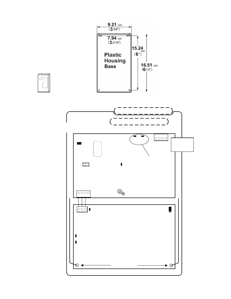
Version 2 Wireless
Antennas enclosed
North American Module
Module Bus
(+
)1
2V
(
-
)0
V
Da
ta A
Da
ta B
ye
llo
w
bl
ac
k
gr
ee
n
re
d
Module Bus
communications
indicator LED
XX
XXX
5 digit serial number
to program in Module
Programming
1
4
3
2
NOTE: DO NOT attempt to
jumper this pin block.
Damage may occur. It is for
the manufacturer’s use only.
Box Tamper Spring
Box Tamper
Enable
Jumper
Radio Antennas
Interconnection
Radio Receiver Board
Interface Board
Valid Decode LED
Decode LED
Diagnostic LEDs
See NA Module Notes.
1
4
3
2
Plastic base cable
inlet knockouts
Back knockout
Side knockout
See NA Module Notes.
See NA Module Notes.
Yellow Green
Box Tamper Enable Jumper must be
removed. See module notes below.
Data Send to Interface board LED
#1 or #2 Receiver Jumper
1
2
Total Current
Consumption
= 75mA
Version 2 Wireless Module
P/N 683-9240
See NA Module Notes.
(Refer to Installation Instructions P/N 22-9240 for further information.)
North American and
European Versions
are in the same
enclosures.