8 and 16 input/output expansion modules, 16 input (8 output) expander module, 8 input (2 output) expander module – Interlogix Monitor XL Hardware Guide User Manual
Page 16
12
Monitor ISM/xL™ Hardware Guide
22-0375 rev1.1
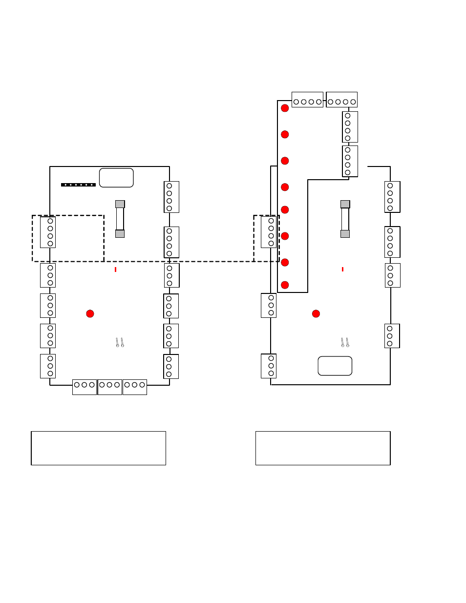
8 and 16 Input/Output Expansion Modules
14
3
2
(+) 12V
Data A
Data B
3
12
14
3
2
F1
1/2
A
M
P
P
/N 3
42-
33
5
6
14
3
2
3
12
3
12
3
12
3
12
3
12
3
12
3
12
0V
COM
COM
COM
COM
COM
COM
COM
COM
I/P1
I/P2
I/P3
I/P4
I/P5
I/P6
I/P7
I/P8
I/P9
I/P10
I/P11
I/P12
I/P13
I/P14
I/P15
I/P16
O/P1
O/P2
Switched (+)
Switched (
-
)
(
-
)
(
-
)
(+) 12V
(+) 12V
(+) 12V
0V
M
o
dul
e Bus
A
u
x
Powe
r
red
green
yellow
black
3
1 2
3
1 2
3
1 2
O/P3
O/
P
4
O/
P
5
O/P6
O/P7
O/
P
8
0V
0V
0V
Tamper Pins
LED 2
follows O/P1
Annunciator
output board
male plug.
TB1
4
TB9
TB5
TB1
TB
6
TB2
TB10
TB11
TB12
TB7
T
B3
T
B
8
TB
4
TB13
16 Input (8 Output) Expander Module
16 Outputs with Annunciator Output Board
14
3
2
Data A
Data B
14
3
2
F1
1/
2
A
M
P
P/
N
34
2-3
3
5
6
14
3
2
3
12
3
12
3
12
3
12
COM
COM
COM
COM
I/P1
I/P2
I/P3
I/P4
I/P8
I/P7
I/P6
I/P5
(
-
)
(
-
)
(+) 12V
(+) 12V
(+) 12V
0V
M
o
dul
e Bu
s
A
u
x
Powe
r
red
green
yellow
black
Tamper Pins
LED 2
follows O/P1
LED 1 Bus
communications
indicator
TB1
4
TB
9
TB1
TB
2
TB3
TB
4
TB13
8 Input (2 Output) Expander Module
10 outputs with Annunciator Output Board
14
3
2
14
3
2
1
4
3
2
1
4
3
2
LED 9
LED 10
LED 11
LED 12
LED 13
LED 14
LED 15
LED 16
O/P9
TB
1
T
B
2
0V
O/P10
0V
O/P11
0V
O/P12
0V
O/P13
O/P14
O/P15
O/P16
0V
0V
0V
0V
TB3
TB4
Annunciator
Output Board
Outputs 3 - 8 do not exist.
LED 1 Bus
communications
indicator
identical
operation
Current rating = 25mA without
annunciator card. 60mA with
annunciator card and all LEDs on.
Current rating = 25mA without
annunciator card. 52mA with
annunciator card and all LEDs on.
5 digit serial number to
program in Module
Programming
5 digit serial
number to
program in Module
Programming
XXXXX
XXXXX
•
The Annunciator Output Board (P/N 650-2660) can be used on either Input / Output module.
•
When used on the 8 Input module, outputs 1 and 2 can be programmed but, in order to program outputs and
LEDs 9 – 16 on the annunciator card, outputs 3 – 8 must be skipped.
•
The 8 Input module must still be assigned 16 outputs in order to program outputs/LEDs 9 – 16 on the annunciator
card.
•
Outputs 1 and 2 are identical operation on both modules.
•
16 Inputs and 16 outputs are available on the 16 Input module using the annunciator card.
Refer to Installation Instructions P/N 22-0363 for
further information.