Interface board, European radio receiver board version, Australian radio receiver board version – Interlogix Monitor XL Hardware Guide User Manual
Page 24
20
Monitor ISM/xL™ Hardware Guide
22-0375 rev1.1
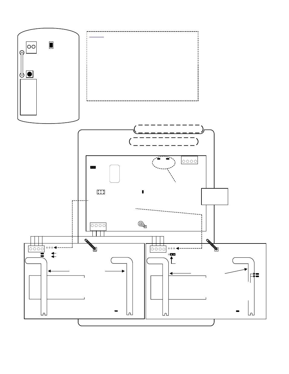
European and Australian Version 2 Wireless Module cont.
Example:
European
Door/Window
Wireless
Contact
Internal View
Tamper
Reed Switch
Reset
Button
Battery
Hardwire Input
Module Bus
(+
)1
2
V
(
-
)0
V
Da
ta
A
Da
ta
B
ye
llo
w
bl
ac
k
gr
ee
n
re
d
Module Bus
communications
indicator LED
X
XXX
X
5 digit serial number
to program in Module
Programming
1
4
3
2
Interface Board Tamper Spring
Tamper
Enable
Jumper
Interface Board
Diagnostic LEDs
1
4
3
2
Plastic base cable
inlet knockouts
Back knockout
Side knockout
See Module notes.
Yellow Green
Tamper Enable Jumper must be
removed. See Module notes.
Total Current
Consumption
= 75mA
Radio Antennas
Decode LED
See Module notes.
Factory Wired
Parallel
Interconnection
TX
RX
Transmit &
Receive to
Interface
Brd LEDs
European
Radio Receiver
Board Version
Radio Brd Tamper Spring
Radio Antennas
Decode LED
See Module notes
Radio Brd Tamper Spring
TX
RX
Transmit &
Receive to
Interface
Brd LEDs
New Zealand
Australia
Ensure the location jumper
selection is in the correct position
NOTE:
NOTE: DO NOT attempt to
jumper these pin blocks.
Damage may occur. They are
for the manufacturer’s use only.
Australian
Radio Receiver
Board Version
Factory Wired
Parallel
Interconnection
Factory Wired Parallel Interconnection
NOTE: Some sensors can have a reed switch and
hardwire input and some can only have a hardwire
input. Check your sensor’s model/part number in
your sales order to ensure you have the correct
version.
A European version door/window sensor has 1
reed switch on its side and one hardwire input.
Both can be used for e.g. 2 doors. However, if only
the reed switch is used, the hardwire input must
be closed with a wire short. If only the hardwire
input is used, the magnet must be installed next to
the reed switch to close the circuit.