Second elevator connections to 2 elevator module, 2 elevator module, 38 monitor ism/xl™ hardware guide – Interlogix Monitor XL Hardware Guide User Manual
Page 42
38
Monitor ISM/xL™ Hardware Guide
22-0375 rev1.1
(+)12V
(
-
)0V
Data B
Data A
14
3
2
1
4
3
2
5
6
1
3
2
1
4
3
2
1
4
3
2
(+)
12V
(
-
)0
V
D
a
ta
A
D
a
ta
B
N.
O
.
Com
.
N.
C.
Com
.
N.
O
.
Co
m
m
on
Co
m
m
on
T
a
m
p
er
Outpu
t
(+
)5
/1
2
V
DC
Gree
n
L
E
D
Re
d L
E
D
Grou
nd 0V
bl
ac
k
ye
llo
w
re
d
g
reen
1
3
2
12
12
2
nd
El
ev D
a
ta
0
N.
O
.
Co
m.
N.
C
.
Co
m
.
N.
O
.
Co
mm
on
By
pas
s
F
ir
e
By
pas
s
C
o
mmo
n
Ta
m
p
e
r O
u
tp
u
t
(+)
5
/12VD
C
Gr
ee
n LED
R
ed
LED
R
e
a
der
1 D
a
ta
1
Gr
oun
d 0V
Rea
der
1
Da
ta
0
P
a
ni
c
I
n
pu
t
1
4
3
2
5 6
1
3
2
1
4
3
2
1
3
2
1 2
1 2
Re
ade
r 2
Da
ta 0
Re
ade
r 2
Da
ta 1
XXXXX
2 Elevator
Module
Self resetting
0.5A fuse.
Low Voltage
LED
Processor OK LED
(normal = slow flash)
Unlock Relay
2 LED
Auxiliary Relay 2 LED
Module Bus communications
indicator LED
Auxiliary
Relay 1 LED
Unlock Relay
1 LED
Reader
Reader
Aux
Rly 2
Aux
Rly 1
Unlock
Rly 1
Unlock
Rly 2
Not Used
Not Used
By
pa
s
s
F
ir
e
By
pas
s
Pan
ic
I
n
put
Module Bus
5V
12V
Reader Voltage
Jumper
5V
12V
Reader Voltage
Jumper
P/N 650-9017
5 digit serial
number to
program in
Module
Programming
red
orange
white
green
black
READER
for
Elevator
Module’s
second
elevator
brown
not used
1
3
2
1
3
2
1 2
1
4
3
2
5
1
2
13
2
RLY1
RLY2
(+)
(
-
)
DATA
DAT
A
DAT
A
0
DAT
A
1
Elevator
Relay Board
Aux
12VDC
(+
)
P
/N
65
0-
90
35
C
u
ta
w
a
y vi
ew
Ea
rth
Co
mm
o
n
Gre
en LED
R
ead
er 1/2 Da
ta
1
R
ead
er
1/2
Da
ta 0
El
ev
1
/2 D
a
ta
0
El
ev1
/2
D
a
ta
In
By
p
a
s
s
Pa
ni
c
In
0V
N
e
g
(
-
)
(+)
12
V
D
C
Gro
und
0V
Co
m
m
o
n
By
pa
s
s
Fir
e
B
y
p
a
ss
Co
m
m
o
n
T
a
m
p
e
r Ou
tput
G
re
en
LED
Re
ade
r 1/
2 D
a
ta
1
Re
ade
r 1/
2 D
a
ta
0
P
ani
c
Ou
t
E
le
v
1/
2 D
a
ta 0
E
le
v
1/
2 D
a
ta 1
El
ev
1/2 Dat
a
I
n
12
VD
C
12
VD
C
Gro
und
0
V
P/
N
641
-9036
12
12
12
3
2
1
4
3
2
1
4
3
2
1
1 2
1 2
1 2
3
2
1
3
2
1
4 5 6
3
2
1
4 5
3
2
1
4 5
(
-
) (+)
(+)
(
-
)
El
ev
1
/2 D
a
ta
1
(
+
)
5 / 1
2
VD
C
Spar
e
Co
mm
o
n
TB1
TB
10
TB4
TB9
TB7
TB3 TB2
TB
13
TB14
TB
1
1
TB12
TB
16
TB
15
0V
Ne
g
0V
N
e
g
Fi
re
B
y
p
a
s
s
Module Bus
connection
from the
motherboard
or paralleling
to another
Module
Power
Supply
(+)
( )
Power
Supply
(+)
( )
Relay and Isolator
board cabinet
12VDC power
supply.
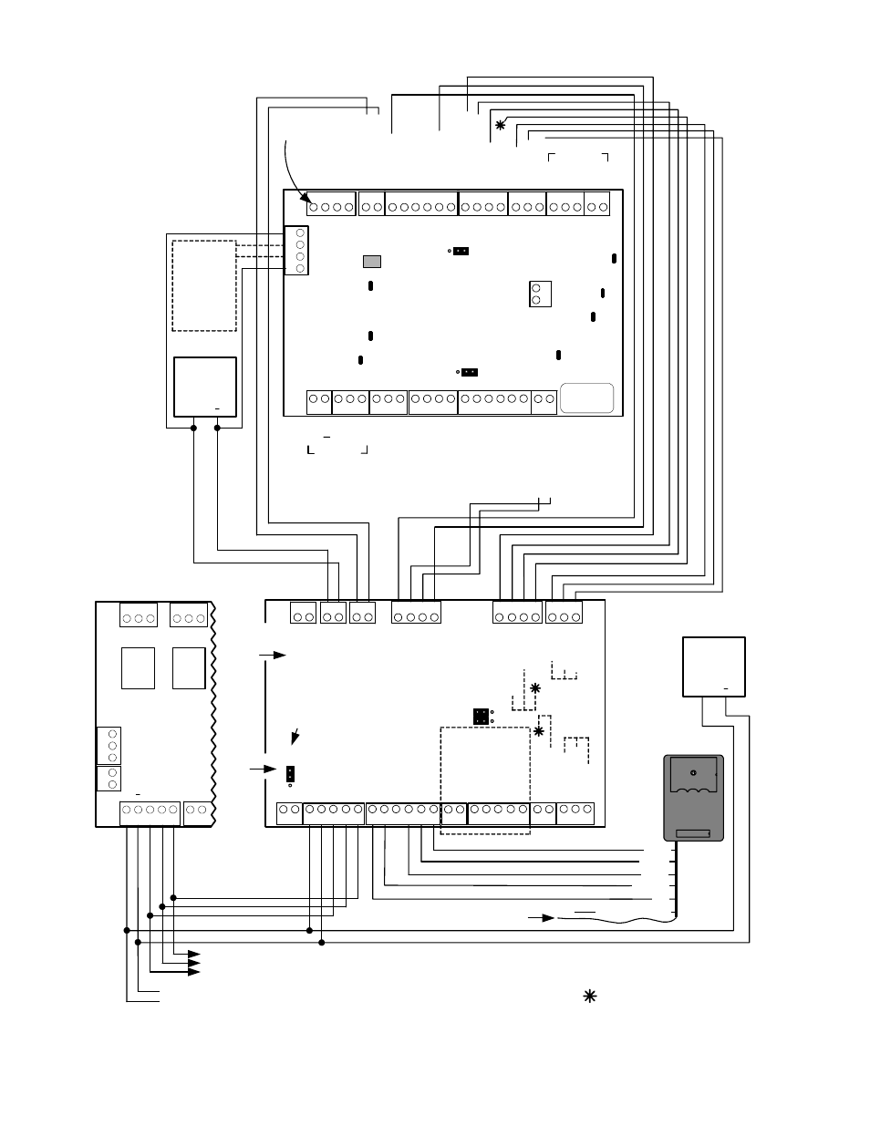
Module Bus
Elevator
Module
12VDC
Power
Supply must
also be
connected to
the Elevator
Module side
of its Isolator
boards.
Elevator
Module
Elevator
side
Elevator
Module
side
Elevator
Isolator
Board
( )
Aux
12
VDC
Reader cable shield. Connect
to control unit ground lug.
Elevator Isolators and Relay boards do not have a 5 digit
serial # to program in Module Programming.
Parallel connections to next Elevator Relay board(s)
Fire Bypass is not intended for
"Life/Safety" applications.
2
nd
El
e
v
D
a
ta
1
1
st
El
ev
D
a
ta
0
1
st
El
ev
D
a
ta 1
2
nd
El
ev
D
a
ta In
1
st
El
ev
D
a
ta
In
ELEVATOR MODULE and ISOLATOR BOARD (2nd elevator connected to 2 Elevator Module)
Reader Voltage
Jumper
5V
1
2
V
Normal
RS485
Second
Elevator
Connections
to 2 Elevator
Module
Reserved for a
Service LCD Keypad
Module
Waterpipe ground input when a
cabinet ground lug is not available.
If quad cable is used, use all four
wires. Terminate two wires in #1
and two wires in #2, for
convenience.
Power to next Elevator Relay board(s) in this cabinet only. NOTE: If more elevator
relay boards are added in additional expansion cabinets with their own power supply -
ALL RELAY BOARD’S POWER SUPPLY NEGATIVES MUST HAVE A COMMON
CONNECTION.
Earth Ground
Gr
oun
d
Elevator Module
current draw =
180mA
.
maximum.
12
Tamper
Switch
Input
RS485 Reader
Connections for
reader runs over 500
ft.
See following
“Wiegand to RS485
Interface Board”