Monitor system reference topics, Adding any power supply to the module bus – Interlogix Monitor XL Hardware Guide User Manual
Page 49
22-0375 rev1.1
Monitor ISM/xL™ Hardware Guide
45
MONITOR System Reference Topics
Adding Any Power Supply to the Module Bus
•
An additional power supply’s positive is not connected to the main control module bus positive with an isolating
diode, as was previously done.
•
The modules using power from the additional power supply have their module bus Data A and B interconnected as
normal.
•
The additional power supply’s negative is connected common to the module bus negative.
•
The additional power supply’s positive is never connected to the module bus positive.
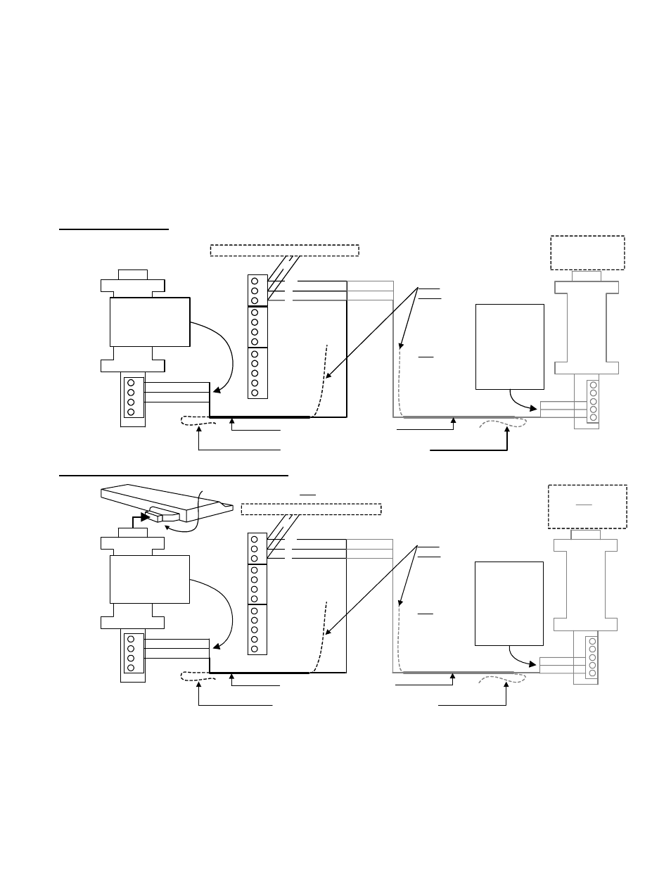
Communication Connections between the Main Controller and the Director PC
Software
Direct Connect to PC
Main
Panel
Mother
board
14
3
2
5
14
3
2
CTS/RTS
RTS/CTS
DSR/DTR
DTR/DSR
RI/RI
CD/CD
TB1
4
TB1
5
green
black
13
2
TB
1
6
0V
B
A
white
RS485
RX/RX
TX/TX
GND/GND
RS485 Communication Cable
Cable shield (do not ground at the PC)
To additional panels (maximum 30)
0V B A
Cable
Shield:
Connect to
the chassis/
earth
ground at
one panel
only (e.g.
1st or last)
black
white
green
NOTE: The
A and B
connections
here are
reversed
relative to
the panel(s).
P/N 120-3401 (24 AWG, 4wires, shielded)
14
3
2
Currently
Supplied
Version
RS485
Converter
P/N
650-9061
DB9 (insert into
free serial port on
the specific PC)
NOTE:
The A and B
connections
are one to one.
DB9 (insert into
free serial port on
the specific PC)
Previous Version
RS485 Converter
P/N 11-0343
(+)12V
(
-
)0V
Data B
Data A
black
green
white
green
black
white
A
B
GND
+12V
GND
Additional power may be needed when
connecting multiple panels. Connect 12VDC
and parallel neg0Vgnd at either converter’s
terminal block.
Modem Connection for PC Communications
Main
Panel
Mother
board
14
3
2
5
14
3
2
CTS/RTS
RTS/CTS
DSR/DTR
DTR/DSR
RI/RI
CD/CD
TB
1
4
TB
1
5
green
black
13
2
TB
1
6
0V
B
A
white
RS485
RX/RX
TX/TX
GND/GND
RS485 Communication Cable
Cable shield (do not ground at the modem)
To additional panels (maximum 30)
0V B A
Cable
Shield:
Connect to
the chassis/
earth
ground at
one panel
only (e.g.
1st or last)
black
white
green
NOTE: The
A and B
connections
here are
reversed
relative to
the panel(s).
P/N 120-3401 (24 AWG, 4wires, shielded)
14
3
2
Currently
Supplied
Version
RS485
Converter
P/N
650-9061
NOTE:
The A and B
connections
are one to one.
Previous Version
RS485 Converter
P/N 11-0343
(+)12V
(
-
)0V
Data B
Data A
black
green
white
green
black
white
A
B
GND
+12V
GND
Connect via DB9-
DB25 and a null-
modem adapter
(or equiv.cable)
MODEM
Connect via DB9-DB25 and a null-modem adapter (or equiv.cable)
Additional power may be needed when
connecting multiple panels. Connect 12VDC
and parallel neg0Vgnd at either converter’s
terminal block.