Interface board radio receiver board, European and australian module – Interlogix Monitor XL Hardware Guide User Manual
Page 23
22-0375 rev1.1
Monitor ISM/xL™ Hardware Guide
19
Flashing slowly. Flashing slowly.
Receiver Failure
The receiver board is not communicating
properly with the interface board. Check the
condition of the three wire interconnection
between the two boards and check power.
Flashing fast,
alternating with
the green LED.
Flashing fast,
alternating with
the yellow LED.
The Module serial
number is not
programmed.
The non-volatile module memory is not
programmed or has failed. If (re)programming
fails, return the module to the factory for a
replacement, .
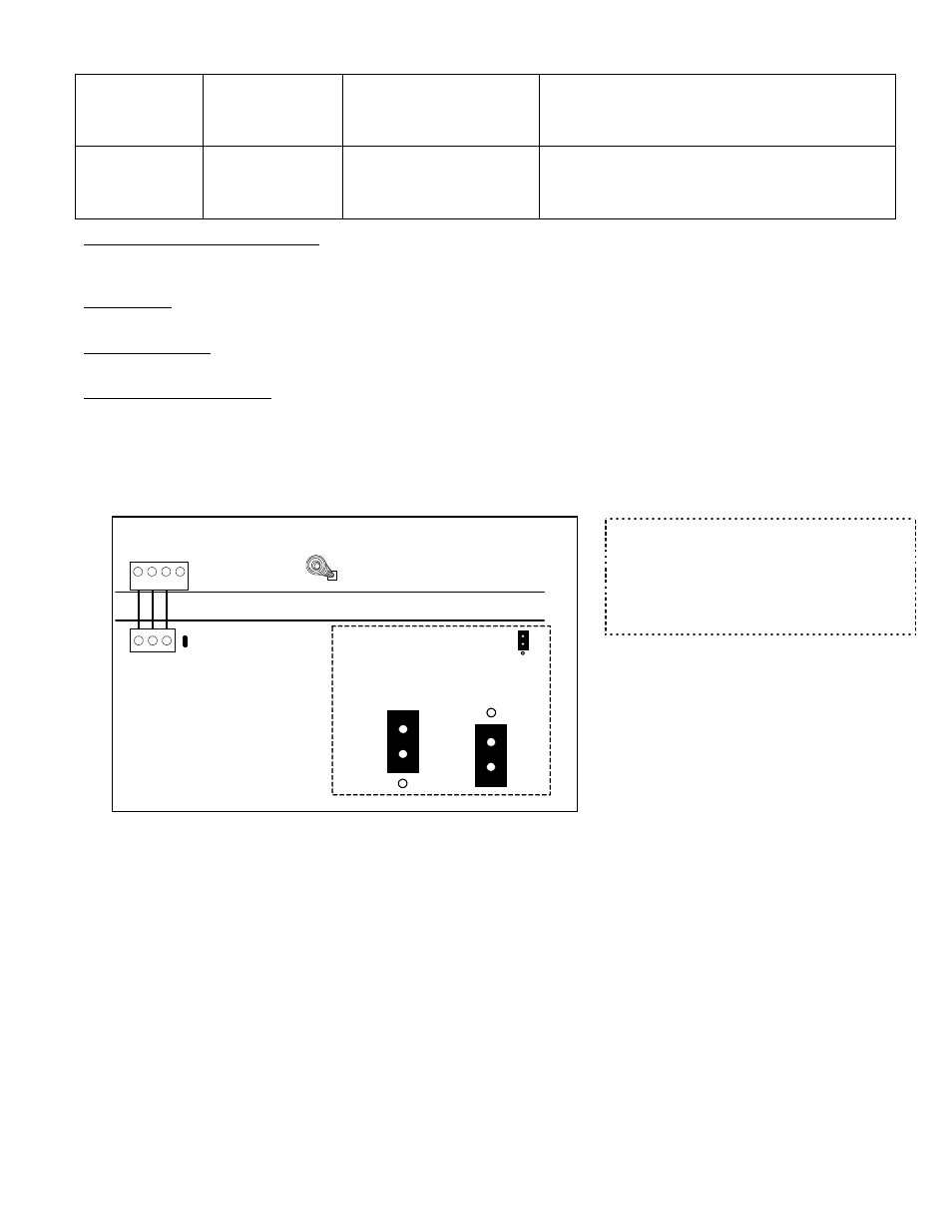
Data Send to Interface Board LED
•
Flashes as data is transmitted to the Interface, which then transmits the information over the module bus to the
main panel.
Decode LED
•
Flashes as any RF data is being received.
Valid Decode LED
•
Flashes as the receiver decodes a message.
# 1 or # 2 Receiver Jumper
•
WARNING: Disconnect the module bus connector, to remove power, before re-positioning this jumper.
•
If it is necessary to mount two receivers close to each other, they must be at least 91.4 cm apart (3 feet).
•
This jumper on one of the receivers must be set in the # 1 position. This jumper on the other receiver must be in the
# 2 position.
•
When there is only one receiver in a general area, this jumper is left in the # 1 position (default).
•
Never leave this jumper out.
1
4
3
2
Box Tamper Spring
Interconnection
Data Send to Interface board LED
#1 or #2 Receiver Jumper
Position 1
Position 2
1
2
Interface Board
Radio
Receiver
Board
Receiver 1
Receiver 2
European and Australian Module
Refer to Euro Installation Instructions P/N 22-9241 and Australian P/N 22-9242 for further information.
•
The EURO and Australian V2 Wireless Modules communicate with Inovonics learn mode EURO wireless sensors.
For each sensor’s instructions, consult the Inovonic’s instructions packed with each sensor.
•
Each EURO and Australian wireless (RF) module supports a maximum of 32 wireless sensors. The V2 wireless
module must be connected to the module bus to enable programming.
•
Mount the module centrally to the wireless sensors.
•
Install module away from large metal objects.
•
Mounting the module on metal surfaces will impair performance.
•
This module is intended for indoor use only. Use in outdoor applications may impair performance.
•
If a sensor reports a ‘low battery’ and the sensor’s battery is replaced, the sensor’s reset button must be pressed to
restore the sensor. Re-check the sensor’s programming to ensure it is correct.
NOTE: If the system’s Feature Set is greater than 5,
Module, Input number Type and Name are
programmed in the Director software program and
sent to the panel. All other wireless sensor
programming described here is done at the system’s
LCD keypad ‘Configs’ screens. Regardless that after
entering Configs, “No Local Edits” displays.