Euro / australian rf repeater module, Version 2 wireless programming – Interlogix Monitor XL Hardware Guide User Manual
Page 25
22-0375 rev1.1
Monitor ISM/xL™ Hardware Guide
21
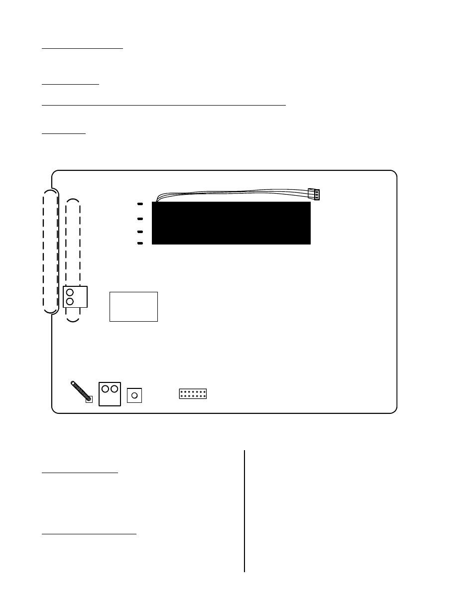
Euro and Australian Wireless Module Notes
Tamper Enable Jumper
•
Dual Tamper Detection:
While the module is de-powered, remove this jumper. When power is applied to the
module, both the Interface and Radio board tampers are active. With the jumper in, only the Radio board’s tamper
is active.
Diagnostic LEDs
Operation is the same as the previously mentioned North American version.
Transmit and Receive data between Interface and Radio Boards, LEDs
•
Flash as data is transmitted between the Interface and Radio boards, which supplies information over the module
bus to the main panel.
Decode LED
•
Flashes as any RF data is being received.
Decode.
(Processing RF
DATA)
Tamper
Spring
(+)12V
(
-
)0V
P
la
s
ti
c base cable
in
let knocko
u
ts
B
a
ck
knock
o
ut
S
ide knockout
Euro / Australian RF Repeater Module
Insert a wire link
(short) in this block
to disable tamper.
Power Input
Total Current
Consumption
= 40mA
Reset
Button
This 7 pin plug not used.
Plug
Re-chargeable Stand-by Battery (12 hr life span)
LEDs
Transmit DATA
Low S/B Battery
Main power on
Press to reinitialize Repeater if all power lost.
NOTE: Re-check the Repeater’s
programming to ensure it is correct.
•
The repeater module is used to increase the range of transmitting and receiving signals.
•
Mounting for the Repeater is the same as the Receiver as it is in the same plastic enclosure. Follow the same
General Information Notes as the Receiver.
Version 2 Wireless Programming
NA and Euro Modules
The version 2 wireless module is very similar to the
version 1 in the way it learns wireless sensors.
•
The V2 does not support wireless keypads and it is
not necessary to reserve input point numbers for
keypad ‘panic’ buttons like V1.
V2 Module Programming
•
The V2 has a 5-digit module serial number, which is
programmed into the system module programming,
like the V1. For systems with a Feature Set of 5 or
above, local configuration programming at an LCD
keypad cannot be done. Module enrollment, input
point assigning, must be done through the Director
software and sent to the panel. V2 wireless sensors
can be learned into the system the same as V1
through the LCD keypad. V1 wireless sensors can
not be used with the V2 module and V2 sensors can
not be used with the V1 module.
•
If for some reason the serial number sticker is
missing, the V2 will display its serial number when it
is first powered. Using the yellow and green LEDs
beside the module bus terminal block, the number
of pulses on the yellow LED while the green LED is
ON, gives the digit value. E.g. green on, count 3