Door controller modules, Version 1 door module, Door 1 door 2 – Interlogix Monitor XL Hardware Guide User Manual
Page 36
32
Monitor ISM/xL™ Hardware Guide
22-0375 rev1.1
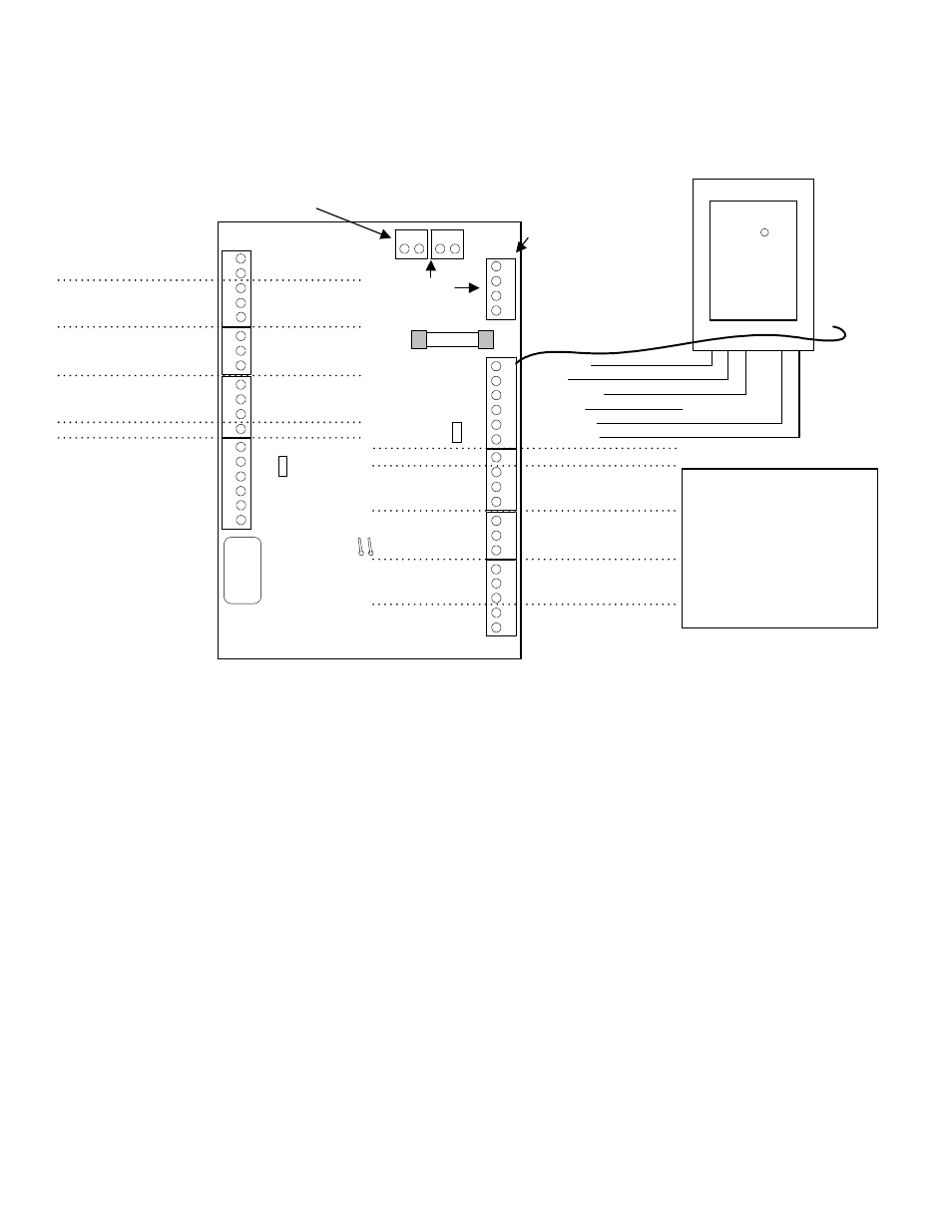
Door Controller Modules
Version 1 Door Module
14
3
2
56
14
3
2
5
13
2
14
3
2
14
3
2
56
14
3
2
5
13
2
14
3
2
14
3
2
1
2
1
2
F1
0.5 AMP
P/N342-3356
Module
Bus
(+
)1
2
V
(
-
)0
V
Dat
a
B
Dat
a
A
(+)12V
(
-
)0V
Data A
Data B
Normally Open
Common
Auxiliary Relay
DOOR
1
DOOR
2
Normally Closed
Common
Normally Open
Auxiliary Input
Door Unlock Relay
Common
Request to Exit
Door Contact Input
Common
Reader Tamper
Reader Buzzer (
-
) Output
...
5V
12V
Reader
Voltage
Jumper
(+)5/12VDC
Green LED
Red LED
Data 1 Clock
Data 0
Ground 0V
Tamper
Pins
Normally Open
Common
Normally Closed
Common
Normally Open
Common
Request to Exit
Door Contact Input
Common
Reader Tamper
Reader Buzzer (
-
) Output
(+)5/12VDC
Green LED
Red LED
Data 1 Clock
Ground 0V
Data 0
Door Unlock Relay
Auxiliary Relay
Read
e
r
R
e
ader
2 DOOR ACCESS
MODULE
Reader
Connection
Example
HID Thin
Line II
Proximity
Reader
yellow, blue, vilolet,
not used
Auxiliary Input
This Module Bus is for trunk
connection from the motherboard
or paralleling to another module
This Module Bus is for
connecting a Service
LCD Keypad Module
ye
llo
w
bl
ac
k
gr
ee
n
re
d
black
yellow
red
green
...
5V
12V
Reader
Voltage
Jumper
TB6
TB7
TB8
TB9
TB5
TB10
TB14
TB1
TB2
TB3
TB4
black
green
white
not used
orange
red
Current Rating
= 60mA min. 180mA with
all 4 relays energized.
Remember to add reader
current. Above reader is
20mA. X 2 = 40mA. This
board's total current could
be 220mA.
Reader cable shield. Connect at
system 0V ground only.
Reader cable
shield. Do not
connect at
reader. Leave
floating.
X
XXXX
5 digit serial
number to
program in
Module
Programming
Refer to Installation Instructions P/N 22-0345 for further information.