Main controller, Main control module, 48 monitor ism/xl™ hardware guide – Interlogix Monitor XL Hardware Guide User Manual
Page 52: Ip module network
48
Monitor ISM/xL™ Hardware Guide
22-0375 rev1.1
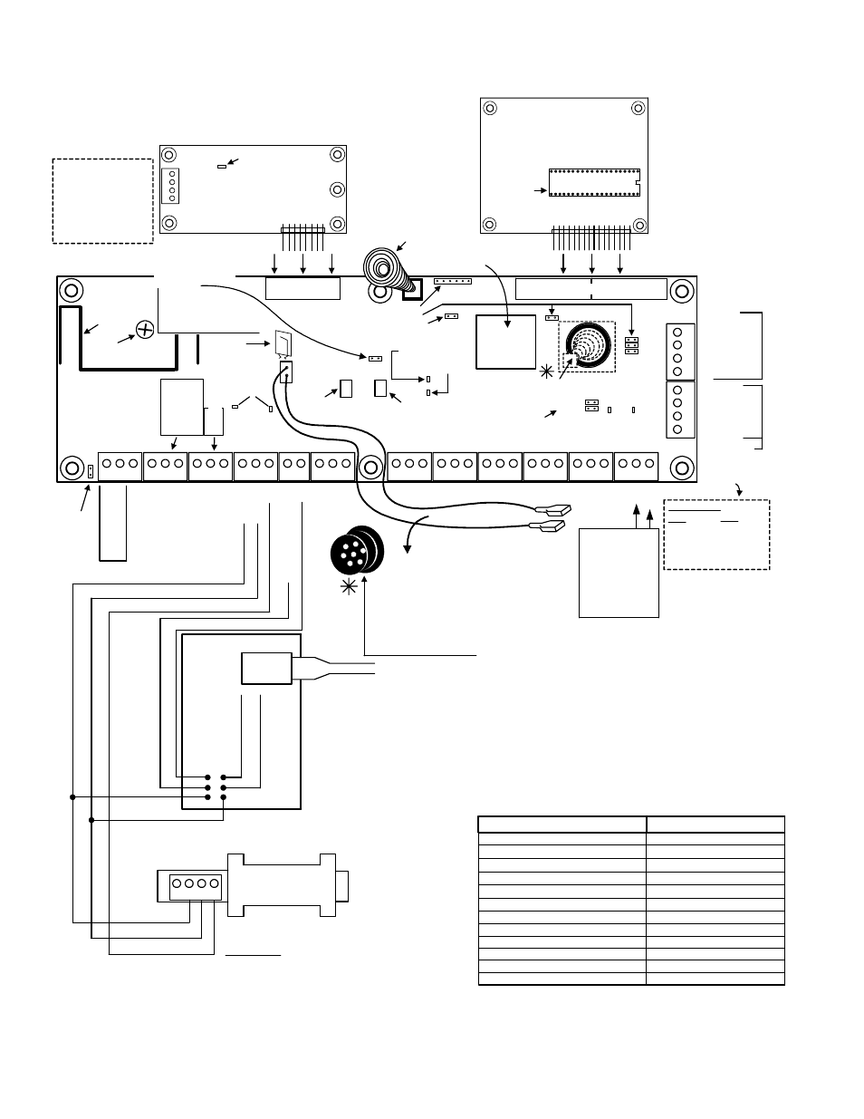
Main Controller
3
1 2
TB2
TB1
3
1 2
3
1 2
3
1 2
1 2
3
1 2
3
1 2
3
1 2
3
1 2
3
1 2
3
1 2
3
1 2
3
12
4
3
12
4
TB3
TB4
TB5
TB6
TB7
TB8
TB9
TB10
TB11
TB12
(+)12V
(
-
)0V
Data B
Data A
bla
ck
red
yello
w
gre
en
(+)12V
(
-
)0V
Data B
Data A
Relay 1
Re
la
y
2
Ea
rt
h
G
N
D
AC
M
a
in
s
AC
M
a
in
s
N
o
rm
a
lly O
p
en
1
Co
mm
on
1
N
o
rm
all
y
Cl
os
ed
1
No
rm
al
ly
O
p
en
2
Com
m
on 2
No
rm
al
ly
Cl
os
e
d
2
Hos
t A
0V
Ho
s
t B
A
u
xi
lia
ry (
+
)1
2
V
D
C
A
u
xi
lia
ry (
+
)1
2
V
D
C
0V
0V
V BU
S
P1
0V
P2
P3
0V
P4
P5
0V
P6
P7
0V
P8
P9
0V
P1
0
0V
P11
P12
Mo
dule B
u
s
(SN
APP)
Mo
dule B
u
s
(SN
APP
)
Input Protection Points
Rear Tamper on back
of board.
Mod Bus (SNAPP)
reset-able fuse.
Battery
power reset-
able fuse.
Momentarily jumper
after a battery has been
connected and there is
no AC mains available.
These unjumpered
connectors for factory
use only. Do not jumper.
Relay 1 is for large
applications such
as a siren. Relay 2
is for smaller ones
such as a strobe.
For module
trunk line.
Grn
TX
Yel
RX
Host
LEDS
Yel
RX
Grn
TX
SNAPP
LEDs
Status Grn LED
Trouble Yel LED
16V
40VA
(+)
(
-
)
Battery Connectors
Auxiliary power
reset-able fuse
(+)
(
-
)
Program Reset
Jumpers
TB13
TB14
Use shielded
cable.
Thi
s
unju
m
pered
c
onnector n
o
t used.
D
o
not j
u
mper.
Battery
leads
plug
TB4 RS485 Host
Communications To
connect to an external
modem, use the 650-
9061 Converter. The
main control board can
not dial out to the
Director software.
Module Bus (shielded)
120-3401
120-3405
Preferred (24 AWG)
FT4
FT6
120-3408
120-3409
ULC (22 AWG)
Terminate shield at
control box earth
ground. Loop through
modules. Do not
terminate at end of line.
Anti-Attack Bushing Cap (p/n 364-5102) covers the rear
tamper spring. It fits inside an “ O “ Ring Bushing (p/n 364-
5103) that fits inside the metal cabinet’s rear wall, anti-tamper
spring, knock-out. Leave the O ring bushing and cap IN if the
rear tamper is not used. If the rear tamper is used, remove the
cap and the O ring with the edge of a flat screw driver. Discard
the O ring. Align the cap to insert in the tamper spring, knock-out
hole on the control cabinet back. Screw the cap by its center hole
to the mounting surface. Place the control cabinet over it,
allowing the rear tamper spring to fit inside the cap. The cap will
insert in the metal cabinet’s tamper spring, knock-out hole.
Complete securing the metal cabinet to the mounting surface.
Position the battery with its terminals
on the left in the control box. Secure
the 12V 7.0Ah battery with the
securing bracket (p/n 232-2605) and
screws from the supplied accessories
kit. For a 17Ah battery bracket, order
kit 250-3617.
during service,
heat sink may
be hot.
To battery 12V 7.0AH
p/n 133-4788
Factory set
Do not adjust
Expansion
Modem
Memory Expansion Socket
Socket
Manual Battery
Re-start
E non volatile memory.
Power loss will not lose
program.
2
Reserve
for service
keypad.
Unpack the Modem and Memory Expansion Modules, if included, in package. With
power disconnected, plug them into the main control board’s Modem and Memory
Expansion Sockets. Secure them to their control cabinet stand-offs with the supplied
screws.
The control box tamper
spring is included in the
accessories kit. Fit it on
to the main board cover
tamper button.
NOTE:
Main Control Module
3
12
4
Seized Tip
Seized Ring
Tip
Ring
Off Hook
LED
North American Modem
Example:
Feature Expansion Module
Memory
Expansion
Socket
Connecting 2 un-
programmed
keypads on the
module trunk will
cause one to
become a service
tool and the other
will not be
accessible. All
programmed
keypads will
function normally.
NOTE: Remove enclosure knock-outs before installing circuit boards.
NOTICE: Use
minimum 26AWG
UL/CSA/or
equivalent
approved
telephone cable.
Turns on when
unit dialing out
(Bell 103)
CAUTION:
P12 is Bell
Return (Siren
Tamper) in UK
configuration. It
is a regular
input in all other
configurations.
Module Description (voltage 12VDC) Current Rating (mA)
LCD Keypad with Reader
North American Modem
8 Output STU
– 110 (includes 10mA /1 o/p)
Worldwide Modem with 8 o/p STU
Feature Expansion Board
– 45
– 115 (includes 10mA / 8 o/p)
– 145 (includes 10mA / 8 o/p)
– 100
LCD Keypad
– 95 (includes 10mA /1 o/p)
8 Transistor Output Board
– 135 (includes 10mA / 8 o/p)
8 Relay Output Board
– 155
16 Point Expander Board
– 100 (includes 10mA / 2 o/p)
8 Input VBUS Expander Board
– 35
8 Point Expander Board
– 85
Power Supply Board
– 50
CFG0
CFG1
MAIN CONTROL MODULE RELAY OUTPUTS
TB2 Relay 1:
5AMPS Resistive, 1 AMP Inductive.
TB3 Relay 2: 1 AMP Resistive,
0.1 AMPS Inductive.
RS485 Communication Cable
Cable Shield: Connect to the chassis/earth ground
at main control box (do not ground at the PC)
P/N 120-3401 (24 AWG, 4wires, shielded)
1
4
3
2
P/N 650-9061
(
+
)12V
(
-
)0V
Data B
Data A
black
green
white
Data A
Data B
(
-
)0V
(+
) 12VDC
O
range
R
S
232 R
X
(S
IP
)
Yellow RS485 B (Dir Sftwr)
Bl
u
e
R
S
232 TX
(S
IP
)
Green
RS485 A
Re
d
Bl
a
c
k
(
-
)
N
eg. G
N
D
IP Module
Network
RS485 Converter
Direct Connect to the Director Software PC
DB9
Plug in to PC
Comms Port
Comms to the Director
Software PC
(Director Sftwr)
S
e
c
u
rity
IP
Re
c
e
iv
e
r